


Page 1521565-3-0906
Thermostats are not approved on vented decorative appliances.
Label all wires prior to disconnection when servicing controls.
Wiring errors can cause improper and dangerous operation. Verify
proper operation after servicing.
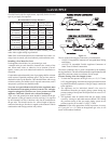
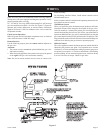
18", 24" and 30" Gas Logs (Millivolt) thermopile is self powered
gas valve and does not require 110 volts. See Figure 17 to provide
optional wall switch, thermostat, or remote control. Maximum
length of 20 feet of 16 AWG to conductor wires is to be used with
all optional switches.
Check System Operation
Millivolt system and all individual components may be checked
with a millivolt meter 0-1000 MV range.
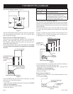
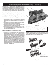
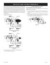
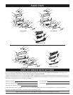
Remote Receiver
Use the following steps to place the remote receiver adjacent to
the gas valve.
Attention:
1. The remote receiver can not be placed behind the gas valve
and burner assembly.
2. When facing the appliance, the remote receiver must be placed
to the right of the gas valve and burner assembly.
Note: Do not let remote control receiver come in contact with
burner assembly.
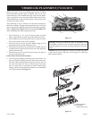
On circulating vent-free firebox, install remote control receiver
behind bottom louver.
Refer to remote control installation and operating instructions for
more details on remote control.
750 Millivolt System
When you ignite the pilot, the thermocouple produces millivolts
(electrical current) which energizes the magnet in the gas valve.
After 30 seconds to 1 minute time period you can release the gas
control knob and the pilot will stay ON. Allow your pilot flame to
operate an additional one (1) to two (2) minutes before you turn the
gas control knob from the PILOT position to the ON position. This
time period allows the millivolts (electrical current) to buildup to a
sufficient level allowing the gas control to operate properly.
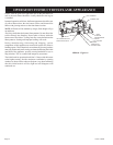
Millivolt Control
The valve regulator controls the burner pressure which should be
checked at the pressure test point. Turn captured screw counter
clockwise 2 or 3 turns and then place tubing to pressure gauge over
test point (Use test point “A” closest to control knob). After taking
pressure reading, be sure and turn captured screw clockwise firmly
to re-seal. Do not over torque. Check for gas leaks.
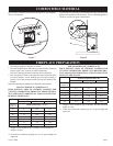
REMOTE/OFF/ON SWITCH
ADISTANCE/FERME/OUVERT
INTERRUPTEUR
IFANY OF THE ORIGINALWIRE
AS SUPPLIED WITH THIS UNIT
MUST BE REPLACED, IT MUST BE
REPLACED WITH NUMBER 18, 150°C
WIRE OR ITS EQUIVALENT.
SI UN DES FILS ELECTRIQUES
ORIGINAUX, VENANT DU FABRICANT
AVEC CETTEUNITE, DOIT ETRE
REMPLACE, VOUS DEVEZ LE
REMPLACERAVEC UN FIL
ELECTRIQUE DE NUMERO 18,
150
°
C DU L'EQUIVALENT.
THERMOPILE
GAS VALVE
THERMOCOUPLE
(NATURAL)
OFF
ON
REMOTE
(OPTIONAL) REMOTE CONTROL RECEIVER
(FACULTATIVE) CONTROLE E DISTANCE
DU RECEPTEUR
(OPTIONAL) WALLSWITCH
INTERRUPTEUR MURAL
(FACULTATIVE)
(OPTIONAL) THERMOSTAT
(FACULATIVE) THERMOSTAT
WIRING DIAGRAM
GAS VALVE
VALVE DE GAZ
REMOTE/OFF/ON SWITCH
ADISTANCE/OUVERT/
FERME INTERRUPTEUR
REMOTE CONTROL RECEIVER/
THERMOSTAT/ CONTROLE E
DISTANCE DURECEPTEUR
H
N
VEILLEUSE
PILOT
THERMOCOUPLE
(LPG)
WIRING
Figure 17