


Page 12 21565-3-0906
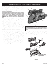
Before you begin: if you are installing logs onto the VFDR18 or
VFDR24 models, this burner assembly is supplied with a set of five
ceramic fiber logs. Do not handle these logs with your bare hands!
Always wear gloves to prevent skin irritation from ceramic fibers.
After handling logs, wash your hands gently with soap and water
to remove any traces of fibers.
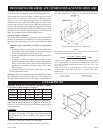
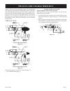
The positioning of the logs is critical to the safe and clean operation
of this burner assembly. Sooting and other problems may result
if the logs are not properly and firmly positioned on the burner
assembly. Refer to Figure 12 and Figure 13 and corresponding
WARNING: when completing following log placement instruc-
tions.
1. Place front logs (#1 and #2) between front grate flange and
main burner. Align notches on front logs with locator tabs in
base.
2. Place middle log (#3) between front and rear loop of burner.
Note: Do not place log on top of pilot assembly.
3. Place rear log (#4) on rear log shelf. Bottom flange of log must
be placed between the log shelf and burner tube.
4. Place front twig (#5) onto (#1) log and flat area on (#3) log.
The bottom of the front twig is to be placed behind the grate
tang that is second from the left.
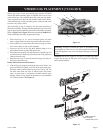
EMBER MATERIAL PLACEMENT ON BURNER
5. After all logs are positioned properly, apply Rockwool ember
material to the front burner port area. To apply, carefully
separate the ember material into small amounts no larger than
"dime size" pieces. Fluffed up pieces one layer thick on top
of the burner generally works best, and will provide the best
ember glow. Do not place ember material more than one layer
thick. No more than (2) two small packets of ember material
(part no. 15998) evenly placed on the burner, is recommended
on VFDR18 and VFDR24 models. Using additional ember
material will decrease the amount of ember glow effect. Extra
ember material should be saved for future ember applications
as necessary. See Figure 13.
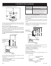
Figure 12
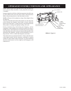
WARNING: Failure to position the parts in accordance with
this diagram or failure to use only parts specifically approved
with this appliance may result in property damage or personal
injury.
Attention: Do not use Figure 12 or Figure 13 to order logs. Refer
to parts list on page 20 and parts view on page 21 to order logs
and/or ember material for your appropriate model.
Figure 13
1
4
5
3
2
EMBER MA
PLACEMENT
(SHADED AREA ONLY)
TERIAL
VFDR(18,24) LOG PLACEMENT (5 LOG SET)