


Page 10 21565-3-0906
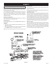
Notice (Damper Clamp Installation)
When installing your log set as a vented installation the damper
clamp must be used.
When installing your log set as a vent-free installation the damper
clamp can be used to eliminate the potential for odors when burning
the logs for the first time.
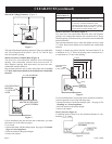
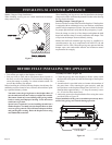
Installing Damper Clamp (Figure 9)
Remove all ashes or other debris from the fireplace. If the fireplace
is equipped with an ash dump be sure to seal the door with furnace
cement or high temperature silicone. Be sure to check the damper
for proper operation and verify that the flue passageway is open.
Place the clamp over the lip of the damper and tighten the hold
down bolt until the clamp is securely attached to the damper. This
will prevent the damper from accidentally closing.
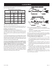
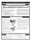
Manual and millivolt controlled gas logs may be installed as a
vented decorative log set in compliance with ANSI Z21.60 and
National Fuel Gas Code. When the gas logs are operated with the
damper open, non-combustible material and minimum mantel
requirements do not apply.
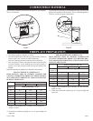
• Turn off the gas supply to the fireplace or firebox.
• Seal any fresh air vents and/or ash clean-out doors located on
the floor or wall of the fireplace. If left unsealed, drafting may
cause pilot outage or sooting. Use a heat resistant sealant. Do
not seal the chimney flue damper.
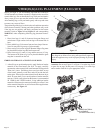
Before installing in a solid fuel burning fireplace, the chimney flue
and firebox must be cleaned of soot, creosote, ashes and loose paint
by a qualified chimney cleaner.
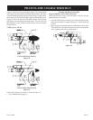
You must secure the gas log heater to the fireplace floor. If
not, the entire unit may move when you adjust the controls.
Movement of unit may cause shifting of the gas logs which
leads to sooting and improper burning. Grate movement
could cause a gas leak.
Special care is required if you are installing the unit into a
sunken fireplace. You must raise the fireplace floor to allow
access to gas log controls. This will insure adequate air flow
and guard against sooting. Raise the fireplace floor using
noncombustible materials.
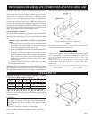
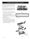
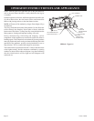
Assembly Procedure: (Figure 10)
1. Center the gas log unit in the fireplace or firebox. Make certain
the front feet of the grate sit inside the front edge of the fireplace
or firebox.
2. An anchor hole is provided in the two bottom side members of
the grate frame. After centering the grate correctly, mark the
hole positions on the fireplace/firebox floor. Drill two (2) 5/32"
diameter holes approximately 1-1/2" deep for masonry screws
or 1/8" hole for sheet metal screws.
3. Anchor the grate to the fireplace/firebox floor using the screws
provided. Refer to Figure 10.
Proper installation of the grate is essential to prevent any move-
ment of the gas logs and controls during operation.
Figure 10
Figure 9
ANCHOR SCREW
LOCATIONS
INSTALLING AS A VENTED APPLIANCE
BEFORE FULLY INSTALLING THE APPLIANCE