


Page 8 16937-4-0806
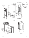
Figure 2 Figure 3 Figure 4
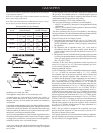
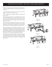
When facing the front of the appliance the following minimum
clearances to combustible construction must be maintained.
Top of appliance (ceiling) 36 inches
Rear Wall 3 inches
Side Wall 6 inches
Heater Corners (45° angle) to Wall 4 inches
Floor 0 inches
CLEARANCES
Provide adequate clearances around air openings.
Adequate accessibility clearances for purposes of servicing and
proper operation must be provided.
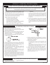
Installation on Rugs and Vinyl
If this appliance is installed directly on carpeting, vinyl or other
combustible material, other than wood flooring, the appliance shall
be installed on a metal or wood panel extending the full width and
depth of the appliance.
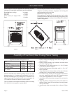
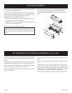
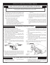
Assembly of Cast Iron (Outer Casing) Stove Casting
Appliance Hardware Package Parts List
Part Part Quantity
Description Number Supplied
1/4-20 x 3/8" Phillips Head Bolt R-3646 8
1/4" 9/32 Washer R-1150 8
10 - 24 Nut R-1118 2
Attention: Included in the hardware package are (8) 1/4" inside
diameter washers. A 1/4" washer may be used with a 1/4-20 x 3/8"
bolt when assembling the stove casting parts. If a bolt hole is not
tapped deep enough for a tight fit between stove casting parts, the
1/4" washer can be used as a shim to provide a tight fit.
The 1/4" washers are not required for assembly of the stove casting
if all the bolt holes are tapped to a proper depth.
1. Remove casting from shipping carton. Place casting on non
-
abrasive surface.
2. Remove burner assembly, logs, hardware and sheet metal
parts from shipping carton.
3. Attach rear cover to casting sides with 1/4 - 20 x 3/8" bolts
(2 per side) as shown in Figure 5.
4. Attach casing bottom to casting sides with 1/4 - 20 x 3/8"
bolts (2 per side).
5. Align and place (2) clearance holes on front legs of burner
assembly over (2) rear weld studs in casing bottom.
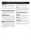
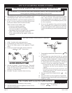
6. For VFCR-25 only, attach green wire to the TH terminal on
gas valve. Attach black wire to the TH/TP terminal on gas
valve from wiring harness on valve cover plate.
7. Attach three (3) knob extensions onto gas valve as shown in
Figure 6.
8. Align and attach (2) clearance holes on MV switch bracket as
shown in Figure 6 onto (2) front weld studs in casing bottom
with (2) 10-24 nuts.
9. Attach casting front onto casting sides as shown in Figure
7.