


Page 1916937-4-0806
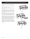
MILLIVOLT OPERATING INSTRUCTIONS
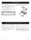
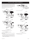
VFCR-25 ON/OFF/REMOTE Switch
VFCR-25 is equipped with an ON/OFF/REMOTE switch which
is located on the wiring chase. A wire harness is attached to the
ON/OFF/REMOTE switch. The brown, black and green (wires)
female push-ons attach to the ON/OFF/REMOTE switch. At the
opposite end of the wire harness, the black and green (wires) female
push-ons attach to the gas valve. An additional brown wire and
the black/red wire, which are stripped and bare, will attach to the
750 millivolt wall thermostat accessory, or, to one of the other
accessories that can be purchased for use with your log set.
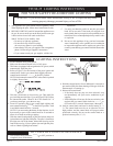
Operation of ON/OFF/REMOTE Switch with no Accessories
To ignite main burner, turn the control knob on the gas valve
from the PILOT position to the ON position. Turn the ON/OFF/
REMOTE switch from the OFF position to the
ON position. The
additional brown wire and black/red wire, which are stripped and
bare are not used.
Operation of ON/OFF/REMOTE Switch with Accessories
750 Millivolt Wall Thermostat
Connect the brown and black/red, stripped and bare, wires on the
ON/OFF/REMOTE switch wire harness to the wall thermostat. Turn
the ON/OFF/REMOTE switch on the valve cover to the REMOTE
position. Set the wall thermostat to the desired temperature.
It is important to use wire of a gauge proper for the length of the
wire:
RECOMMENDED WIRE GAUGES
Maximum Wire
Length Gauge
1' to 10' 18
10' to 25' 16
25' to 35' 14
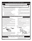
750 Millivolt System
When you ignite the pilot, the thermocouple produces millivolts
(electrical current) which energizes the magnet in the gas valve.
After 30 seconds to 1 minute time period you can release the gas
control knob and the pilot will stay ON. Allow your pilot flame to
operate an additional one (1) to two (2) minutes before you turn the
gas control knob from the PILOT position to the ON position. This
time period allows the millivolts (electrical current) to build-up to
a sufficient level allowing the gas control to operate properly.
Wall Switch, FWS-1
Connect the brown and black/red, stripped and bare, wires on
the ON/OFF/REMOTE switch wire harness to the wall switch.
Turn the ON/OFF/R
EMOTE switch on the valve cover to the
REMOTE position. Pivot the rocker switch on the FWS-1 to the
ON position.
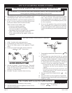
Battery Operated Remote Control, FRBC-1 and FRBTC-1
Connect the brown and black/red, stripped and bare, wires on the
ON/OFF/REMOTE switch wire harness to the remote receiver
that is a component in the FRBC-1 and FRBTC-1. Turn the
ON/OFF/REMOTE switch on the valve cover to the REMOTE
position. Follow instructions in the FRBC-1 and FRBTC-1 to
complete installation.
Note: If batteries fail in FRBC-1 or FRBTC-1, and immediate
heat is desired, turn the ON/OFF/REMOTE switch on valve cover
from the REMOTE position to the ON position.
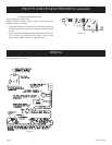
Wiring of ON/OFF/REMOTE Switch with 750 Millivolt Wall
Thermostat Accessory and Another Accessory
Connect the brown and black/red, stripped and bare, wires on the
ON/OFF/REMOTE switch wire harness to the 750 millivolt wall
thermostat AND to the remote receiver that is a component in the
FRBC-1 OR to the FWS-1, wall switch.
1. Connect (1) wire from the 750 millivolt wall thermostat and
(1) wire from appropriate accessory to the BROWN, stripped
and bare wire from the ON/OFF/REMOTE wire harness.
2. Connect (1) wire from the 750 millivolt wall thermostat and (1)
wire from appropriate accessory to the BLACK/RED, stripped
and bare wire from the ON/OFF/REMOTE wire harness.
Note: When the appliance is in the MANUAL mode and the
batteries fail in the FRBC-1 and immediate heat is desired,
turn the ON/OFF/REMOTE switch on valve cover from the
REMOTE position to the ON position.
Manual Operation
1. Turn ON/OFF/REMOTE switch on valve cover to REMOTE
position.
2. Turn wall thermostat OFF.
3. Turn accessory, FRBC-1 or FWS-1, ON. Appliance is now in
the manual mode. You must turn the appliance ON or OFF with
appropriate accessory.
Wall Thermostat Operation
1. Turn the ON/OFF/REMOTE switch on valve cover to REMOTE
position.
2. Turn accessory, FRBC-1 or FWS-1, OFF.
3. Turn wall thermostat ON and set appropriate temperature. Wall
thermostat will cycle the appliance ON and OFF.
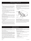
Installation of Remote Receiver
1. The remote receiver can not be placed behind the gas valve
and burner assembly.
2. When facing the appliance, the remote receiver must be placed
to the left of the gas valve and burner assembly.
Refer to remote control installation and operating instructions for
more details on remote control.