


16942-5-0907Page 16
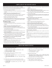
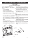
1. Spark electrode does not produce spark.
a. Spark electrode broken - replace.
b. Ignitor wire may not be attached to spark electrode - attach.
c. Ignitor wire damaged - replace.
d. Piezo ignitor defective - replace.
2. Spark electrode produces spark but pilot does not light.
a. No gas to heater - turn on gas.
b. PILOT position not properly aligned - turn gas control knob to
PILOT position and depress.
c. Pilot is blocked from spider web or dirt - clean pilot, see Page
15.
3. Pilot flame does not stay "ON" when control knob is released.
a. Control knob in PILOT position not completely depressed or held
in long enough.
b. Thermocouple not tightened into gas control - tighten
thermocouple.
c. Pilot flame not surrounding thermocouple - clean pilot, see Page
15.
d. Inlet gas pressure too low, contact gas supplier.
e. Thermocouple defective - replace.
f. Gas control defective - replace.
4. Main burner does not ignite.
a. Main burner orifice is blocked - clean, see "Main Burner Flame
Characteristics," Page 14. Attention: The number stamped on the
main burner orifice is a millimeter diameter.
b. Inlet gas pressure too low, contact gas supplier.
5. Heater keeps shutting "OFF" during normal operation.
a. Pilot is blocked - clean pilot, see Page 15.
b. Inlet gas pressure too low, contact gas supplier
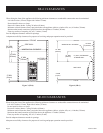
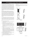
Removing Pilot/Thermocouple From Main Burner Assembly
Attention: The thermocouple CAN NOT be replaced as an individual item.
You must order a new pilot when replacing thermocouple.
1. Turn OFF gas supply to the heater.
2. Turn OFF electrical supply to the heater if optional blower is installed
in heater.
3. Remove lower louver from casing assembly (2 screws).
4. Remove reflector from casing assembly (2 screws).
5. Disconnect pilot tubing from pilot (see Figure 18, Page 15). Grasp nut
A with a wrench when removing nut B with a second wrench.
6. Remove pilot from pilot bracket (2 screws).
7. Remove thermocouple lead from gas valve.
8. As parts are being replaced in reverse order, check for gas leaks at all gas
connections before lower louver is replaced onto casing assembly.
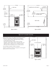
Removing Main Burner Orifice(s) From
Main Burner Assembly
1. Turn
OFF gas supply to the heater.
2. Turn OFF electrical supply to the heater if optional blower is installed
in heater.
3. Remove lower louver from casing assembly (2 screws).
4. Remove reflector from casing assembly (2 screws).
5. Remove pilot bracket from main burner assembly (2 screws).
6. Pivot pilot bracket with attached pilot away from main burner assembly
(do not damage pilot tubing).
7. Disconnect supply tubing from orifice holder(s).
8. Remove orifice holder from venturi of main burner assembly (1 screw
for each orifice holder).
9. Remove main burner orifice from orifice holder. Attention: The number
stamped on the main burner orifice is a millimeter diameter.
10. As parts are being replaced in reverse order, check for gas leaks at all gas
connections before lower louver is replaced onto casing assembly.
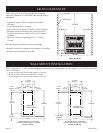
Removing Manual Gas Control From Casing Assembly
1. Turn
OFF gas supply to the heater.
2. Turn
OFF electrical supply to the heater if optional blower is installed
in heater.
3. Remove lower louver from casing assembly (2 screws).
4. Remove reflector from casing assembly (2 screws).
5. Disconnect inlet supply tubing, outlet supply tubing, pilot supply
tubing and thermocouple lead from manual gas control.
6. If heater is attached to wall, disconnect gas supply line from inlet
regulator.
7. Remove heater from wall.
8. Remove cotter pin from manual gas control rod.
9. Remove manual gas control bracket from casing assembly (3 screws
to be removed are located on casing assembly back).
10. Loosen nut that secures manual gas control to bracket. Remove manual
gas control from bracket.
11. As parts are being replaced in reverse order, check for gas leaks at all
gas connections before reflector and lower louver are replaced onto
casing assembly.
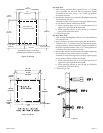
Removing Main Burner From Casing Assembly
1. Turn
OFF gas supply to the heater.
2. Turn OFF electrical supply to the heater if optional blower is installed
in heater.
3. Remove lower louver from casing assembly (2 screws).
4. Remove reflector from casing assembly (2 screws).
5. Disconnect supply tubing from orifice holder(s).
6. Remove pilot bracket from main burner assembly (2 screws).
7. Remove main burner assembly from casing assembly (4 screws).
8. Remove orifice shield from main burner assembly. Attach orifice shield
to new main burner assembly.
9. As parts are being replaced in reverse order, check for gas leaks at all gas
connections before lower louver is replaced onto casing assembly.
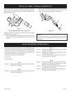
Piezo Pilot Ignitor Instructions
Depressing the ignitor button completely causes a spark to occur at the
pilot.
To light the pilot, it is important that the electrode be 1/8" (3mm) from
the pilot. The spark must occur at the point the pilot flame hits the
thermocouple.
On a new installation with air in the gas line, it is suggested that a match
be used. The match will light the pilot faster than the piezo under this
condition.
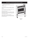
APPLIANCE MAINTENANCE
TROUBLESHOOTING