


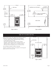
16942-5-0907Page 8
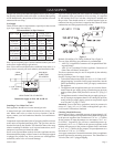
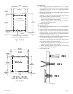
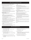
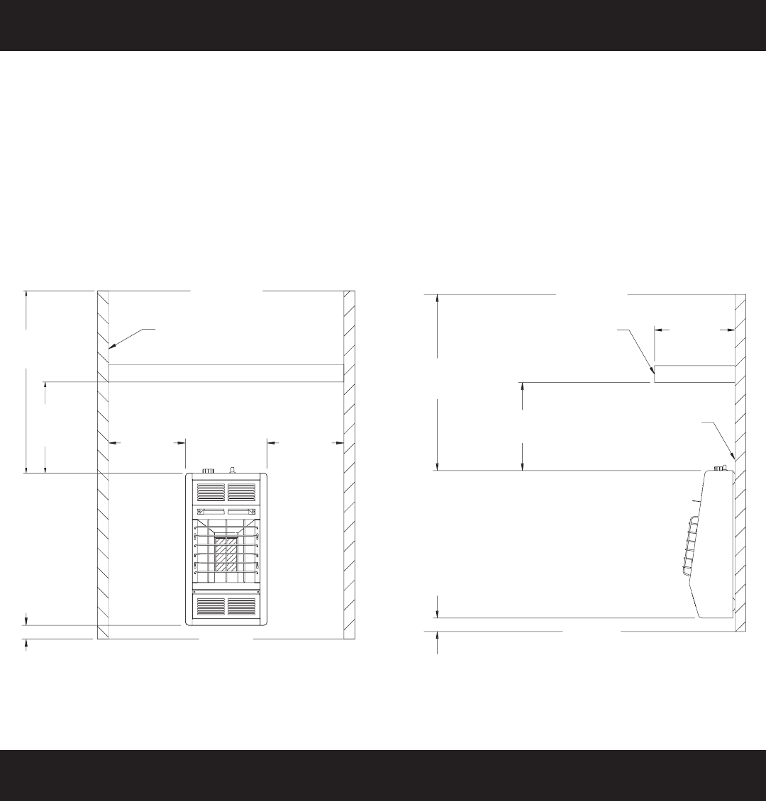
Figure 3 (SR-6)
When facing the front of the appliance the following minimum clearances to combustible construction must be maintained.
Left side 6 inches (152mm). Right side 6 inches 152mm).
Do not install in alcove or closet.
Rear wall 0 (0mm) inches. Ceiling 24 inches (610mm).
Minimum vertical clearance from a projection above the appliance (shelves, window sills, etc.) 10 inches (254mm).
Maximum horizontal extension of projection above the appliance 12 inches (305mm).
Floor (top surface of carpeting, tile, etc.) 2 inches (51mm).
Provide adequate clearances around air openings.
Adequate accessibility clearances for purposes of servicing and proper operation must be provided.
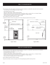
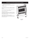
Figure 4 (SR-6)
CEILING
WINDOW SILL OR SHELF
24” MIN
(610mm)
10” MIN
(254mm)
12” MAX
(305mm)
0” (0mm) CLEARANCE
TO REAR
WALL
SIDE VIEW
2” MIN
(51mm)
FLOOR
CEILING
SIDE
WALL
WINDOW SILL OR SHELF
24” MIN
(610mm)
10” MIN
(254mm)
6” MIN
(152mm)
6” MIN
(152mm)
2” MIN
(51mm)
FLOOR
When facing the front of the appliance the following minimum clearances to combustible construction must be maintained.
Left side 6 inches (152mm). Right side 6 inches (152mm).
Do not install in alcove or closet.
Rear wall 0 inches (0mm). Ceiling 24 inches (610mm).
Minimum vertical clearance from a projection above the appliance (shelves, window sills, etc.) 14 inches (356mm).
Maximum horizontal extension of projection above the appliance 12 inches (305mm).
Floor (top surface of carpeting, tile, etc.) 2 inches (51mm).
Provide adequate clearances around air openings.
Adequate accessibility clearances for purposes of servicing and proper operation must be provided.
SR-6 CLEARANCES
SR-10 CLEARANCES