


16942-5-0907 Page 23
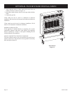
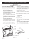
INSTALLING OPTIONAL BLOWER SRB-18 OR SRB-30
If heater is installed onto the wall, in order to install the optional blower,
the heater must be removed from the wall. If heater is installed on op
-
tional floor stand there is adequate access area available to install the
optional blower.
1. Turn “OFF” gas supply to the heater.
2. Remove lower louver from casing assembly (2 screws).
3. Remove reflector from casing assembly (2 screws).
4. Remove upper louver from casing assembly (2 screws).
5. Remove on/off switch knockout from the casing assembly top.
6. Insert the on/off switch wires through the casing assembly top. The
on/off switch wires will enter the top portion of the casing assembly.
Snap on/off switch into the casing assembly top.
7. Route cord set through 9/16” (14mm) diameter hole on casing
assembly back. Insert approximately 3” (76mm) of cord set into
casing assembly back.
8. When you are facing the front of the heater, position the optional
blower assembly onto the top heat shield of the heater. The motor
wire harness should be facing into the top, right portion of the
heater.
9. Attach (1) pin terminal from black (hot) wire, smooth insulation on
cord set to (1) socket terminal from the on/off switch.
10. Attach (1) pin terminal from black (neutral) wire, ribbed insulation
on cord set to (1) socket terminal from white (neutral) wire on motor
wire harness.
11. Attach (1) pin terminal from the on/off switch to (1) socket terminal
from black (hot) wire on motor wire harness.
12. Attach the green ground wire from the motor wire harness and the
green ground wire from the cord set to the bottom right side of the
blower housing with (1) screw provided with the optional blower.
13. With the heater standing upright, position the air discharge opening
of the blower housing downward. Place the bottom flange of the
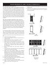
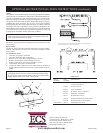
OPTIONAL BLOWERS
SRB-18 and SRB-30
for Unvented Room Heaters SR-18 and SR-30
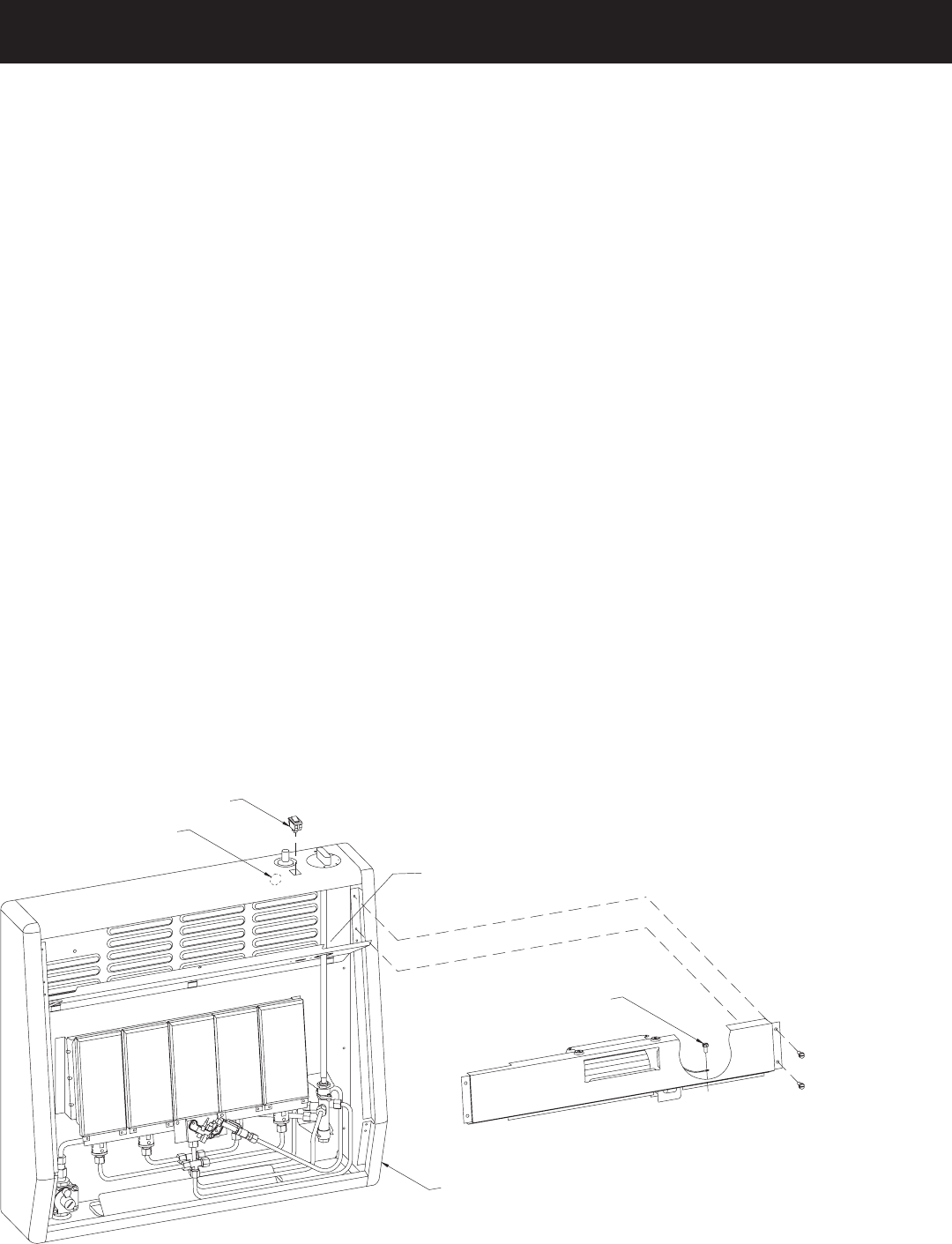
HEAT SHIELD
GROUND
WIRE
SCREW
REFLECTORAND LOUVERSARE
REMOVED FROMCASING
ASSEMBL
Y
ON/OFF
SWITCH
CORD
SET
HOLE
IN
CASING BAC
K
blower housing over the top edge of the top heat shield. Insert the
blower housing into the top portion of the heater by pivoting the
blower housing upward 90°. Attach the blower housing to the casing
assembly with (4) screws provided with the optional blower.
14. Grasp cord set at casing assembly back and pull excess cord set
through casing assembly back. Secure cord set in casing assembly
back with the strain relief provided with the optional blower.
15. Installation of optional blower is completed.
16. If heater was removed from the wall, in order to install optional
blower, check for gas leaks at all gas connections before lower
louver is replaced onto casing assembly.
Attention! After optional blower has been installed use the following
steps to properly align the upper louver and the reflector with the heat
shield.
A. When replacing upper louver, be sure the bottom lip of upper louver
goes behind the heat shield.
B. When replacing reflector, be sure the top lip of reflector goes in front
of the heat shield.
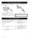
Excessive Blower Wheel Noise
ATTENTION! If your blower assembly develops a squeal, hum or
grinding noise, it indicates dirt or debris on shaft of blower wheel. Use
the following steps to clean shaft of blower wheel.
1. Remove red rubber grommet with brass bushing or black rubber
grommet with brass bushing from end of blower wheel shaft
opposite motor.
2. Clean blower wheel shaft with cotton cloth.
3. Place 1 or 2 drops of all purpose oil on END of blower wheel shaft.
4. Replace red rubber grommet with brass bushing or black rubber
grommet with brass bushing onto end of blower wheel shaft.
Attention: The red rubber grommet with brass bushing or the
black rubber grommet with brass bushing must “snap-back” into
position.
5. Cleaning of blower wheel shaft is completed.
SR-30 Shown
OPTIONAL BLOWER INSTALLATION INSTRUCTIONS