


Page 10 20101-0-0306
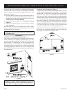
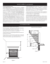
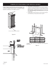
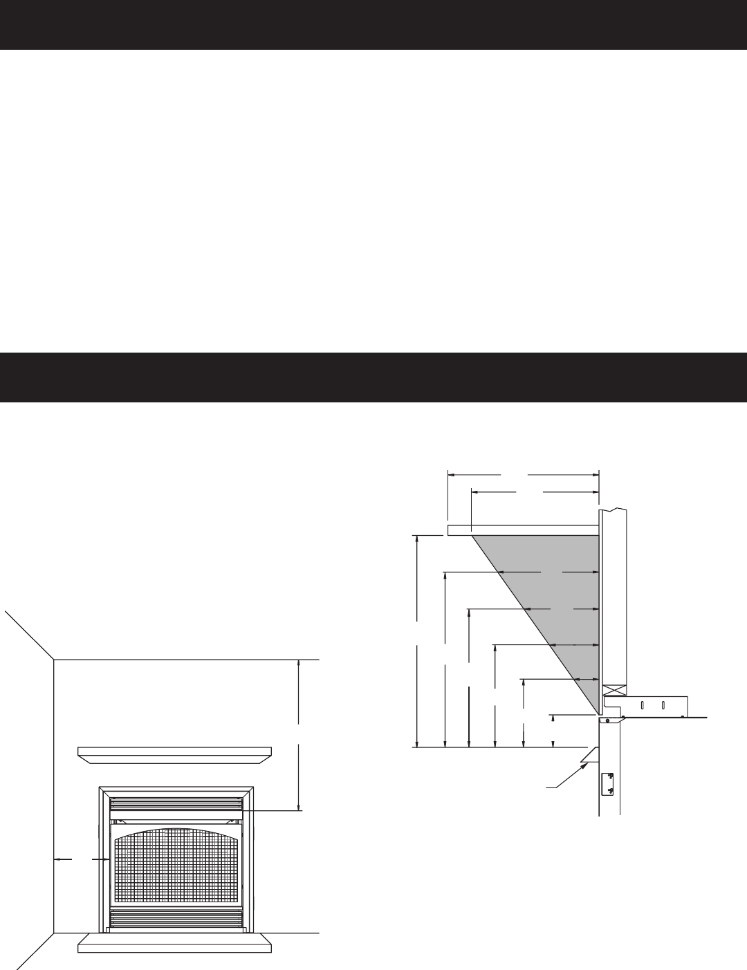
Minimum Wall and Ceiling Clearances (Figure 4)
Sidewall Clearances: The clearance from the inside of the fireplace
to any combustible wall should not be less than 2".
Fireplace Side and Back Clearances: The fireplace outer casing
sides and back have zero clearance to combustibles.
Ceiling Clearances: The ceiling height should not be less than 36"
from the top of the hood.
Mantel Clearances: Vent free fireplace models must use the hood
supplied with the fireplace. If a combustible mantel is installed,
it must meet the clearance requirements detailed above.
Figure 4
2”
36
”
COMBUSTIBLES
ALLOWED
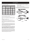
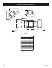
MANTEL
HOOD
2”
7”
4”
9 3/4”
4 1/4”
6”
12 ½”
8”
15 1/4”
18”
10”
12”
Figure 5
Mantel Clearances (Figure 5)
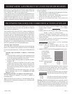
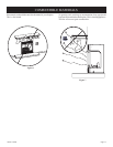
Checking Manifold Pressure
VFP(32,36)FP(30,31)LN (Natural gas) will have a manifold
pressure of approximately 3.5" w.c. (.871kPa) for maximum input or
1.7" w.c. (.423kPa) for minimum input at the pressure regulator outlet
with the inlet pressure to the pressure regulator from a minimum
of 4.5" w.c. (1.120kPa) for the purpose of input adjustment to a
maximum of 10.5" w.c. (2.614kPa). VFP(32,36)FP(20,21)LN
(Natural gas) will have a manifold pressure of approximately 6.0"
w.c. (1.49kPa) at the pressure regulator outlet with the inlet pressure
to the pressure regulator from a minimum of 7.0" w.c. (1.74kPa)
for the purpose of input adjustment to a maximum of 10.5" w.c.
(2.615kPa). VFP(32,36)FP(30,31)LP (Propane gas) will have a
manifold pressure approximately 10.0"w.c. (2.49kPa) for maximum
input or 4.9"w.c. (1.220kPa) for minimum input at the pressure
regulator outlet with the inlet pressure to the pressure regulator
from a minimum of 11.0"w.c. (2.739kPa) for the purpose of input
adjustment to a maximum of 13.0"w.c. (3.237kPa).
VFP(32,36)FP(20,21)LP (Propane gas) will have a manifold
pressure approximately 10.0"w.c. (2.49kPa) at the pressure
regulator outlet with the inlet pressure to the pressure regulator
from a minimum of 11.0"w.c. (2.739kPa) for the purpose of input
adjustment to a maximum of 13.0"w.c. (3.237kPa).
A test gage connection is located downstream of the gas appliance
pressure regulator for measuring gas pressure. The connection is
a 1/8 inch (3mm) N.P.T. plugged tapping.
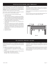
VFP(32,36)FP(30,31) Millivolt Control
The valve regulator controls the burner pressure which should be
checked at the pressure test point. Turn captured screw counter
clockwise 2 or 3 turns and then place tubing to pressure gauge
over test point (Use test point “A” closest to control knob). After
taking pressure reading, be sure and turn captured screw clockwise
firmly to re-seal. Do not over torque. Check for gas leaks.
GAS SUPPLY (continued)
CLEARANCES