


Page 20 20101-0-0306
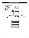
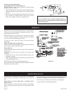
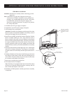
Figure 17
Warning:
Never use needles, wires, or similar cylindrical objects to
clean the pilot to avoid damaging the calibrated ruby that
controls the gas flow.
Cleaning and Pilot Maintenance
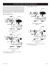
Oxygen Depletion Sensor Pilot (Figure 17)
When the pilot has a large yellow tip flame, clean the Oxygen
Depletion Sensor as follows:
1. Clean the ODS pilot by loosening nut B from the pilot tubing.
When this procedure is required, grasp nut A with an open end
wrench.
2. Blow air pressure through the holes indicated by the arrows.
This will blow out foreign materials such as dust, lint and
spider webs. Tighten nut B also by grasping nut A.
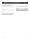
Label all wires prior to disconnection when servicing controls.
Wiring errors can cause improper and dangerous operation. Verify
proper operation after servicing.
Millivolt thermopile is self powered, gas valve does not require
110 volts. Maximum length of 20 feet of 16 AWG to conductor
wires is to be used with all optional switches.
Use the two leads (Red and Green) to attach optional
components.
Check 750 Millivolt System Operation
Millivolt system and all individual components may be checked
with a millivolt meter 0-1000 MV range.
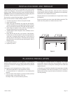
Remote Receiver
Use the following steps to place the remote receiver adjacent to
the gas valve.
Attention: The remote receiver bracket is not used in this
installation.
1. The remote receiver can not be placed behind the gas valve
and burner assembly.
2. When facing the appliance, the remote receiver must be placed
to the right of the gas valve.
Install remote control receiver behind bottom louver.
Refer to remote control installation and operating instructions for
more details on remote control.
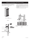
Keep the control compartment, logs and burner area surrounding
the logs clean by vacuuming or brushing area at least twice a
year.
THE LOGS CAN GET VERY HOT – HANDLE ONLY
WHEN COOL.
Always turn off gas to the pilot before cleaning. For relighting,
refer to lighting instructions located on the rating plate of the
log set.
Never obstruct the flow of the combustion and ventilation air. Keep
the front of the fireplace clear of all obstacles and materials.
Leave at least 36" clearance from the front of the fireplace.
Screens should be closed during operation.
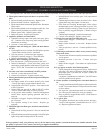
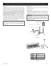
Figure 1
8
REMOTE/OFF/ONSWITCH
ADISTANCE/FERME/OUVERT
INTERRUPTEUR
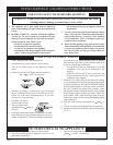
IFANYOFTHEORIGINALWIRE
ASSUPPLIEDWITHTHISUNIT
MUSTBEREPLACED,ITMUSTBE
REPLACEDWITHNUMBER18, 150°C
WIREORITSEQUIVALENT.
SIUNDESFILS ELECTRIQUES
ORIGINAUX,VENANTDUFABRICANT
AVECCETTEUNITE,DOITETRE
REMPLACE,VOUSDEVEZLE
REMPLACERAVECUNFIL
ELECTRIQUEDENUMERO18,
150
°
CDUL'EQUIVALENT.
THERMOPILE
GASVALVE
THERMOCOUPLE
(NATURAL)
OFF
ON
REMOTE
(OPTIONAL)REMOTECONTROLRECEIVER
(FACULTATIVE)CONTROLEEDISTANCE
DURECEPTEUR
(OPTIONAL)WALLSWITCH
INTERRUPTEURMURAL
(FACULTATIVE)
(OPTIONAL) THERMOSTAT
(FACULATIVE) THERMOSTAT
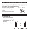
WIRING DIAGRAM
GASVALVE
VALVEDEGAZ
REMOTE/OFF/ONSWITCH
ADISTANCE/OUVERT/
FERMEINTERRUPTEUR
REMOTECONTROLRECEIVER/
THERMOSTAT/CONTROLEE
DISTANCEDURECEPTEUR
H
N
VEILLEUSE
PILOT
THERMOCOUPLE
(LPG)
WIRING
MAINTENANCE