


Page 24 20101-0-0306
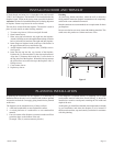
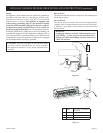
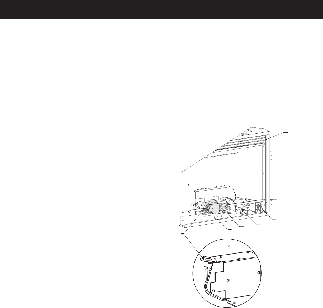
FBB4 Blower Installation
Attention: Install blower assembly before connecting gas inlet
supply line.
Note: Junction box on right side of fireplace must be pre-
wired at time of fireplace installation for use with blower
assembly. It is recommended that an ON/OFF wall switch
be installed that will activate the power supply to the
furnace by a qualified electrician. See page 26 for junction
box wiring instructions
1. If installed, turn OFF gas supply to fireplace.
2. If applicable, turn OFF electric supply to fireplace.
3. Lower bottom louver on fireplace.
Attention: If installed, do not damage gas inlet supply line when
blower assembly is inserted into fireplace. If necessary, removal
of the gas inlet supply line may be necessary.
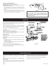
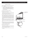
4. Insert blower assembly into interior, bottom of fireplace. Position
blower assembly behind gas valve, align notch on back of
blower assembly with center screw on fireplace back and push
blower assembly against fireplace back. The blower wheel must
be centered with the back wall of the fireplace. Place blower
assembly against the back wall. The magnets on the back and
bottom of blower assembly will sufficiently hold blower assembly
in place.
5. Position speed control box to the right of gas valve. Attach speed
control box to bottom of fireplace. The magnets on the bottom
of speed control will sufficiently hold the speed control box in
place.
6. With base (flush face) of fan control switch facing upward, insert
base flanges of fan control switch under the mounting tabs on
valve bracket. The base (flush face) of fan control switch must
be in contract with bottom of the firebox.
7. Insert power cord plug into junction box.
8. Close bottom louver on fireplace.
Note: This blower is equipped with a heat activated fan control
switch. Fan will operate when the fireplace warms up, and will
turn off when the fireplace cools down.
9. Installation of FBB4 optional variable speed blower assembly
is completed.
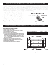
Figure 19
VALV
EBRACKET
F
AN
SWITCH
FA
NKIT
SPEEDCONTROL
JUNCTION
BOX
SWITCH
HOLDER
(TOP
OFVALV
EBRACKET)
SEE NOT
E
OPTIONAL
BLOWER
INST
ALLATIO
N I
S
I N T E N D E
D F O R
LOUVERED
MODELS
ONLY.
OPTIONAL VARIABLE SPEED BLOWER INSTALLATION INSTRUCTIONS