


16943-5-0806 Page 9
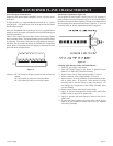
On Sheet Rock Wall
1. After locating mounting holes, drill (4) 5/16" (8mm) diameter
holes into the wall.
2. Insert (4) plastic expansion anchors provided into the
holes.
3. Tighten (4) #10 x 1" (25mm) screws provided into the plastic
expansion anchors. Do not completely tighten screwheads
to the plastic expansion anchors, leave a 1/8" (3mm) gap
between screwheads and plastic expansion anchors.
4. Mount heater onto the (4) screwheads and complete tightening
the screwheads to the plastic expansion anchors.
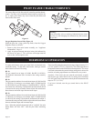
Attention! Use the following steps to properly align the upper
louver and the reflector with the heat shield.
a. When replacing upper louver, be sure the bottom lip of
upper louver goes behind the heat shield.
b. When replacing reflector, be sure the top lip of reflector
goes in front of the heat shield.
5. Connect the gas line.
Figure 8
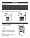
OUTLINE OF
OUTER CASING
MOUNTING HOLE LOCATIONS
VIEWED FROM FRONT OF HEATER
FLOOR
2” (51mm) MIN.
2 1/32” (52mm)
4 1/32”
(102mm) MIN.
18 7/8”
(479mm)
1 3/32”
(28mm)
24 1/8” (613mm)
20 1/8” (511mm)
2”
(51mm)
2”
(51mm)
22”
(559mm)
BF-30
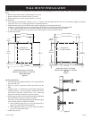
Figure 7
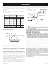
BF-10 and BF-20
Figure 6
Refer to Figures 6 and 7 for measurements in order to locate (4) mounting holes on wall. Figures 6 and 7 are the front views of the
heater.
1. Remove lower louver from casing assembly (2 screws).
2. Remove reflector from casing assembly (2 screws).
3. Remove upper louver from casing assembly (2 screws).
On Solid Wall
1. After locating mounting holes, attach (4) #10 x 1" (25mm) screws provided into the wall. Do not completely tighten screwheads
to the wall, leave a 1/8" (3mm) gap between screwheads and wall.
2. Mount heater onto the (4) screwheads and complete tightening screwheads into the wall.
Attention! Use the following steps to properly align the upper louver and the reflector with the heat shield.
a. When replacing upper louver, be sure the bottom lip of upper louver goes behind the heat shield.
b. When replacing reflector, be sure the top lip of reflector goes in front of the heat shield.
3. Connect the gas line.
18” (457mm)
14” (356mm)
2”
(51mm)
2”
(51mm)
1 3/32”
(28mm)
18 7/8”
(479mm)
OUTLINE OF
OUTER CASING
4 1/32”
(102mm) MIN.
2 1/32” (52mm)
MOUNTING HOLE LOCATIONS
VIEWED FROM FRONT OF HEATER
FLOOR
2” (51mm) MIN.
22
”
(559mm)
WALL MOUNT INSTALLATION