


Page 8 16943-5-0806
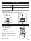
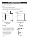
SRS-18* and SRS-30 Floor Stand Installation
1. Align clearance holes on floor stand with screw holes on
bottom of heater, as shown in Figure 5.
2. Attach floor stand to heater with (4) screws provided with
floor stand.
3. Connect the gas line.
* SRS-18 floor stand can not be used in a bedroom
installation.
BF-10 must be wall mounted in a bedroom installation.
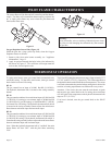
Installation on Rugs and Tile
If this appliance is installed directly on carpeting, tile or other
combustible material, other than wood flooring, the appliance shall
be installed on a metal or wood panel extending the full width and
depth of the appliance.
Attention: Optional SRS-18 and SRS-30 Floor Stand meets
requirement.
The base referred to in this section does not mean the fire-proof
base as used on wood stoves. The protection is for rugs that are
extremely thick and light colored tile.
Figure 5
BF-30
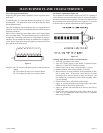
Figure 4
BF-10 and BF-20
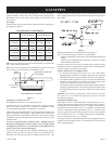
Figure 3
When facing the front of the appliance the following minimum clearances to combustible construction must be maintained.
Do not install in alcove or closet.
Provide adequate clearances around air openings.
Adequate accessibility clearances for purposes of servicing and proper operation must be provided.
BF-10/BF-20 BF-30
Left side 5" (127mm) 8" (203mm)
Right side 5" (127mm) 8" (203mm)
Rear wall 0" (0mm) 0" (0mm)
Ceiling 36" (914mm) 36" (914mm)
Minimum vertical clearance from a projections above
the appliance (shelves, window sills, etc.)
36" (914mm) 36" (914mm)
Floor (top surface of carpeting, tile, etc.) 2" (51mm) 2" (51mm)
CLEARANCES
OPTIONAL FLOOR STAND INSTALLATION