


16943-5-0806 Page 13
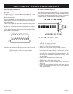
Glass Removal, Cleaning and Glass Replacement
1. Remove chrome grill from reflector.
2. Slide glass upward to remove glass from chrome grill.
3. Clean glass with a non-abrasive household glass cleaner and
warm water. Gas fireplace glass cleaner can also be used.
4. Align glass with rails on chrome grill and slide glass downward
into chrome grill.
5. Attach chrome grill onto reflector.
Warning: Do not operate unvented room heater without glass/
chrome grill attached to reflector.
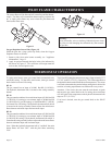
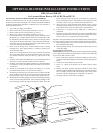
To Remove Pilot From Main Burner Assembly
1. Turn OFF gas supply to the heater.
2. Turn OFF electrical supply to the heater if optional blower,
SRB-18T or SRB-30T is installed in heater.
3. Remove lower louver from casing assembly (2 screws).
4. Remove reflector from casing assembly (2 screws).
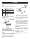
5. Disconnect pilot tubing from pilot (see Figure 12, Page 12).
Grasp nut A with a wrench when removing nut B with a second
wrench.
6. Remove pilot from pilot bracket (2 nuts).
7. As parts are being replaced in reverse order, check for gas
leaks at all gas connections before lower louver is replaced
onto casing assembly.
To Remove Main Burner Orifice From
Main Burner Assembly
1. Turn off gas supply to the heater.
2. Turn off electrical supply to the heater if optional blower,
SRB-18T or SRB-30T is installed in heater.
3. Remove lower louver from casing assembly (2 screws).
4. Remove reflector from casing assembly (2 screws).
5. Disconnect supply tubing from orifice holder.
6. Remove orifice holder from venturi of main burner assem-
bly.
7. Remove main burner orifice from orifice holder.
8. As parts are being replaced in reverse order, check for gas
leaks at all gas connections before lower louver is replaced
onto casing assembly.
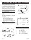
To Remove Gas Valve From Casing Assembly
1. Turn
OFF gas supply to the heater.
2. Turn OFF electrical supply to the heater if optional blower,
SRB-18T or SRB-30T is installed in heater.
3. Remove lower louver from casing assembly (2 screws).
4. Remove reflector from casing assembly (2 screws).
5. Remove upper louver from casing assembly (2 screws).
6. If installed, remove optional blower assembly (4 screws).
7. Disconnect inlet supply tubing, outlet supply tubing, pilot
supply tubing and thermocouple lead from gas valve.
8. If heater is attached to wall, disconnect gas supply line from
inlet regulator.
9. Remove heater from wall.
10. Remove gas valve bracket from casing assembly (4 screws to
be removed are located on casing assembly back).
11. Remove hydraulic thermostat bulb from thermostat bulb clip
located at casing assembly bottom.
12. Remove gas valve from gas valve bracket.
13. As parts are being replaced in reverse order, check for gas leaks
at all gas connections before upper louver, reflector and lower
louver are replaced onto casing assembly.
To Remove Main Burner From Casing Assembly
1. Turn
OFF gas supply to the heater.
2. Turn OFF electrical supply to the heater if optional blower,
SRB-18T or SRB-30T is installed in heater.
3. Remove lower louver from casing assembly (2 screws).
4. Remove reflector from casing assembly (2 screws).
5. Disconnect supply tubing from orifice holder.
6. Remove main burner assembly from casing assembly (2
screws).
7. Remove air shutter(s) from main burner. BF-10 Natural and
LP has two (2) air shutters, BF-20 LP has one (1) air shutter
and BF-30 LP has one (1) air shutter. Attach air shutter(s) to
new main burner assembly.
8. As parts are being replaced in reverse order, check for gas
leaks at all gas connections before lower louver is replaced
onto casing assembly.
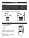
APPLIANCE MAINTENANCE