


Product Data Document
1660DS-7c
July 17, 2007 - Page 7
Bristol
®
ControlWave
®
XFC
Remote Automation Solutions
Website: www.EmersonProcess.com/Remote
High Speed Counter Inputs
Number of points: 2
Input Range: Internally source dry contact input
Frequency range: 0 – 10,000 Hz
Input ltering: 20 microseconds
One shot pulse conditioned signal to MSP
counter
Signal Conditioning: Debounce circuit for
contact closures and bandwidth limiting for
counter input
Input current: 200uA
“0” state voltage: Above 1.5V
“1” state voltage: Below 1.5V
Electrical isolation: None
Surge Suppression: 30V transorb between
signal and ground meets ANSI/IEEE C37.90-
1978
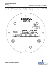
Terminations: Pluggable Terminal block
accommodates up to 14 gauge wire size
Analog Inputs
Point Count: 3 Inputs, Single ended
Range: 1-5 Vdc, externally powered
Input Impedance: 1 M ohm
Filter: single pole
Accuracy +/- .1% of full scale at 25ºC; +/- .2%
of full scale from -20 to 70ºC; +/- .3% of full
scale from -40 to 80ºC
Maximum Scan Rate: once per second
Surge Suppression: 9V transorb between
signal and ground meets ANSI/IEEE C37.90-
1978
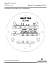
Terminations: Pluggable Terminal block
accommodates up to 16 gauge wire size
•
•
•
•
•
•
•
•
•
•
•
•
•
•
•
•
•
•
•
•
Analog Output
Point Count: One analog output
Range: 4-20mA Sink
Maximum drive for 4-20 mA output: 450 Ohms
Resolution: 16-bits
Accuracy: +/- 0.1% of full scale at 25ºC; +/-
0.2% of full scale from -20 to 70ºC, +/- 0.3% of
full scale; -40 to 80ºC
Maximum Update Rate: once per second
Surge Suppression: 9V transorb between
signal and ground meets ANSI/IEEE C37.90-
1978
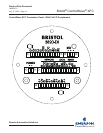
Terminations: Pluggable Terminal block
accommodates up to 16 gauge wire size
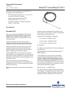
RTD Interface Information
A three-wire platinum RTD per DIN 43760 is sup-
ported. The temperature, T, in degrees Celsius is
calculated using the Resistance vs. Temperature
Tables according to the DIN EN 60751 standard for
Class A & B RTDs. The DIN EN 60751 equation is:
R(t) = R
0
* (1 + At +Bt
2
)
Where:
A = 3.9083 * 10
-3
o
C
-1
B = -5.775 * 10
-7
o
C
-2
R
0
= 100ohms
In addition, the user may enter the R
0
, A, and B
coefcients of a custom calibrated RTD, another
platinum standard or a different material (Nickel,
Balco or Copper).
During the RTD calibration, the user will be able to
set the coefcients, restore the factory default for
these coefcients, and calibrate the internal Refer-
ence resistor.
RTD Input Specications
These specications are for the interface only, not
including the RTD probe or wiring (please note that
•
•
•
•
•
•
•
•