Reference Manual
IP2013, Rev BA
February 2012
3-5
Mobrey MSP422
Mounting the Transmitter
Above the Liquid Surface
A 2-in. thread is provided to mount the transmitter. The thread form is either
2-in. BSPT or 2-in. NPT, and is clearly marked on the hexagon of the
transmitter body.
NOTE:
The Mobrey MSP422 is designed to be mounted in a non-metallic fitting or
flange. The use of metallic fittings/flanges is not recommended.
To help installation, flange accessories and bracket kits are available from
Mobrey.
Procedure:
1. Ensure that the transmitter is perpendicular to the liquid surface to
maximize the return echo size.
2. Check that the maximum liquid level will not enter the 12-in. (0,3 m)
blanking zone of the transmitter.
3. When installing in a tank with a nozzle or stand-off
(Figure 3-2 on page 3-6):
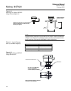
a) Use PTFE tape on the screw thread (Figure 3-2 on page 3-6).
b) Lower transmitter into the tank through the process connection.
c) Turn the transmitter until it is properly secured in the process
connection (Figure 3-2 on page 3-6).
d) Tighten to a torque of 1.5 lbf.ft (2 Nm) using the hexagon. Do not use
the transmitter housing to tighten.
NOTE:
If the transmitter face does not protrude into the vessel, note the dimensions
in Table 3-1 for Figure 3-2, and ensure that the nozzle/vessel weld is smooth
and free from internal weld beads or other projections.
4. When installing using a bracket kit (Figure 3-3 on page 3-6):
a) Attach bracket to the disc using the 3 screws provided.
b) Attach bracket and disc to a support. The combined weight of bracket
and disc is 16 oz (0,5 kg). For transmitter weight, see "Specifications"
on page A-1.
c) Use PTFE tape on the screw thread of the transmitter
(Figure 3-2 on page 3-6).
d) Insert the transmitter into the disc.
e) Tighten to a torque of 1.5 lbf.ft (2 Nm) using the hexagon. Do not use
the transmitter housing to tighten.
NOTE:
The bracket kit contains a stainless steel angle bracket and PVC threaded
disc, which may be used to mount the transmitter on a support over the liquid
surface. The bracket and disc dimensions are in Figure A-4 on page A-4.


