


6
Wiring Your Heat Fan
NOTE: If you feel that you do not have
enough electrical wiring knowledge or
experience, have your fan installed by a
licensed electrician.
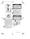
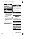
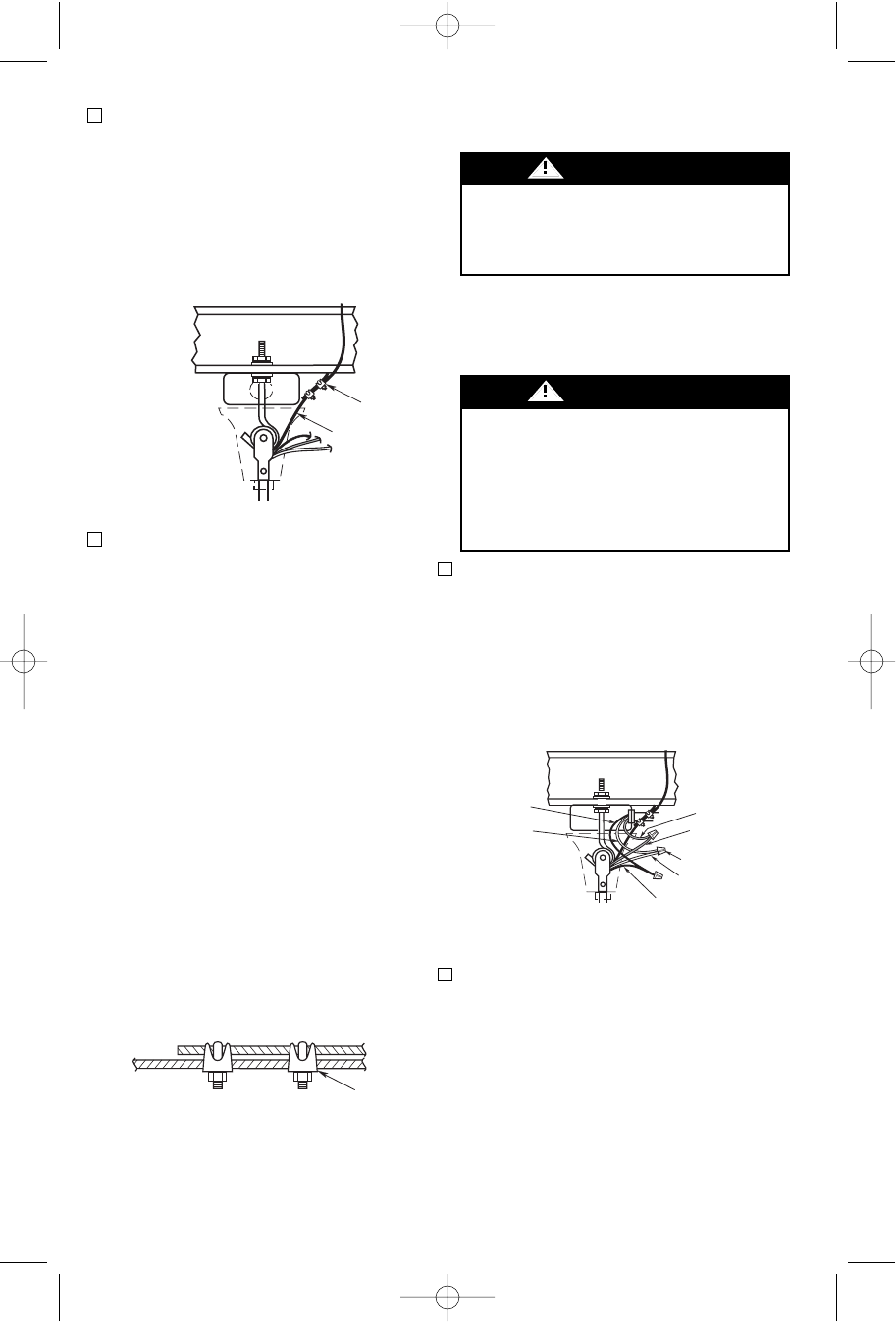
1. Connect the green grounding wire from
the fan motor to the green grounding
wire from the supply source. Securely
connect wires with wire connectors
supplied. (See Figure 9.)
CAUTION: Use larger U.L. listed wire
connectors if supply source wires are
larger than #12 AWG.
2. Securely connect the fan motor white
wire to the supply white (neutral) wire
using a wire connector supplied (Figure
9). Securely connect the fan motor
black wire to the supply black (hot) wire
using wire connector supplied. After
connections have been made, turn
leads upward and carefully push leads
into the outlet box, with the white and
green leads on one side of the outlet
box and the black leads on the other
side of the outlet box.
To avoid possible fire or electrical shock,
do not pinch wires between the hanger
ball/downrod assembly and hanger
bracket.
WARNING
To avoid possible electrical shock, be
sure electricity is turned off at the main
fuse box before wiring.
NOTE: If you are not sure if the outlet box
is grounded, contact a licensed
electrician for advice, as it must be
grounded for safe operation.
WARNING
GROUND WIRE
BLACK SUPPLY
(HOT)
BLACK FAN WIRE
GREEN WIRE (GROUND)
FROM FAN
WIRE CONNECTORS (3)
WHITE SUPPLY
(NEUTRAL)
WHITE FAN WIRE
Figure 9
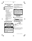
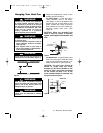
2. Lift the fan onto the J-hook and position
as shown in Figure 7. Make sure the
motor wires and retention cable at the
top of the hanger pipe are positioned
behind J-hook as illustrated in Figure 7.
CAUTION: The electrical wires and
retention cable must not be placed
between the rubber roller and the hook,
but rather as illustrated in Figure 7.
3. This fan is equipped with the required
retention cable. This cable must be
affixed to the building structure and
securely clamped in such a manner to
support the weight of the fan in the
event the mounting hook or other parts
fail. After wrapping cable around or to a
structural member that will support 50
pounds, secure cable with supplied
cable clamps as illustrated in Figure 8.
NOTE: Leave approximately 3" but no
more than 5" of slack on this safety
cable to allow for possible fan
movement. Do not exceed more than 5"
total slack.
CAUTION: It is important to note the
proper installation position of the cable
clamps as illustrated in Figure 8. To
obtain maximum holding power, install
U-bolt section of clip on dead or short
end of cable and saddle on long end of
cable. Improper installation reduces
the efficiency of the connection by as
much as 40 percent.
CABLE
CLAMPS
RETENTION
CABLE
Figure 7
TO SUPPORT
STRUCTURE
TO
FAN
CABLE
CLAMPS
Figure 8
U.L. Model No.: HF948, HF956
BP7311 48 56" Heat Fans 1/16/08 10:52 AM Page 6