


Preset Memory Feature
Your Emerson remote control receiver is equipped
with a preset memory feature. If the electrical supply
to the receiver is controlled through a wall switch,
when the switch is turned off, the control will
remember the light intensity and fan speed. When the
switch is turned back on, the light and fan will resume
operation as they were prior to the switch being
turned off.
Setting Remote Control
Operating Frequency
Your Emerson Remote Control Fan transmitter can be
set to operate at one of 16 different frequencies. In
most cases you will not need to change the factory
set frequency. The frequency should only need to be
changed for one of the following reasons:
a. Multiple fans in one location that you wish to
operate from one transmitter. (ALL fans should be
set at the same frequency.)
NOTE: Your Emerson Remote Control is designed
to operate from a distance up to 20 feet from the
fan. If you are operating multiple fans with one
transmitter you should be no more than 20 feet
from any of the fans to ensure that all fans will
respond at the same time.
b. Multiple fans in one location that you wish to
operate from different transmitters. (ALL fans set to
different frequencies.)
c. Interference with other household systems such as
your garage door opener.
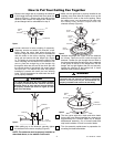
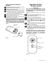
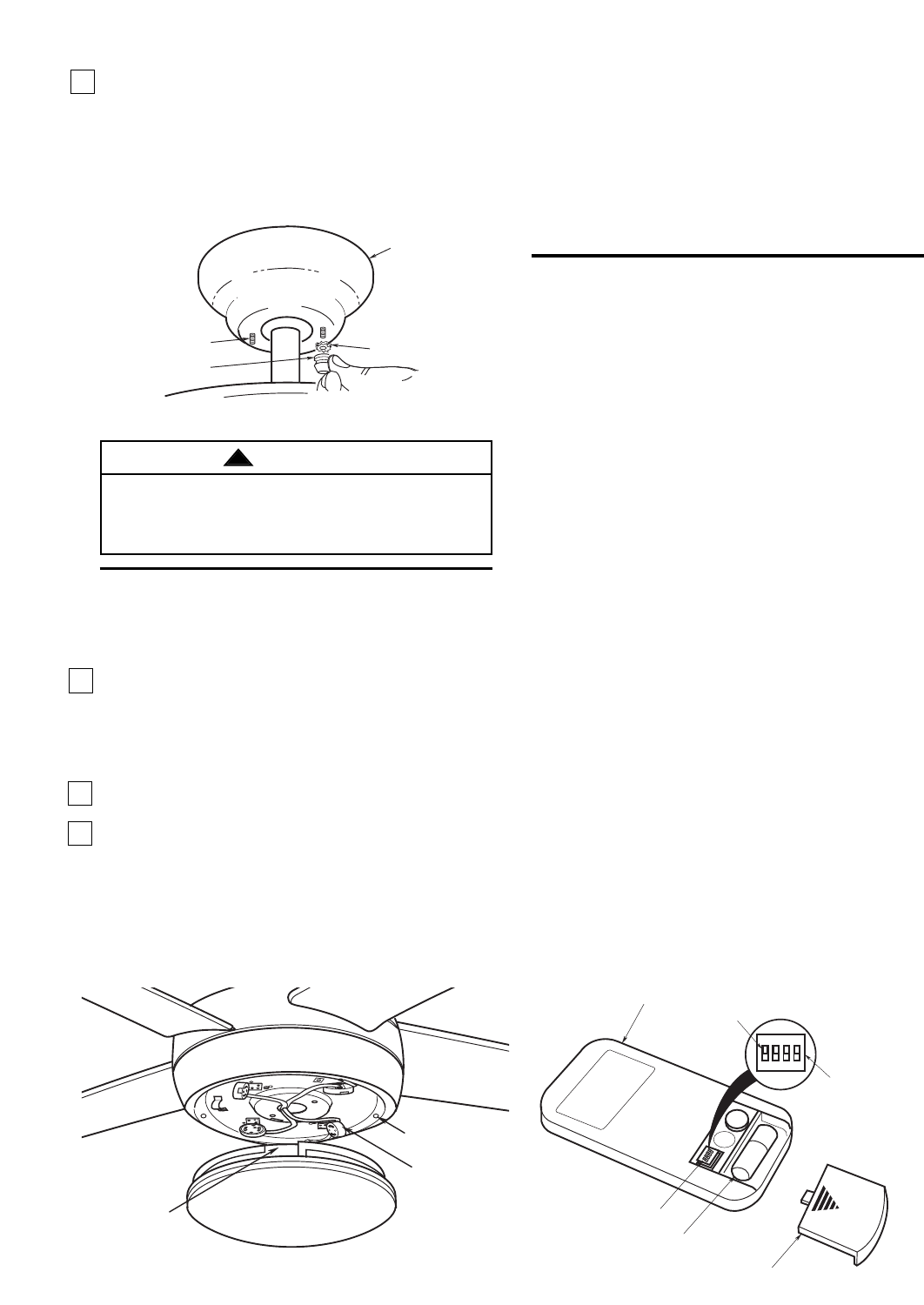
Setting Transmitter Frequency
1. Remove battery cover from the transmitter. Locate
the switch with four levers numbered 1, 2, 3, 4, just
above the battery compartment (See Figure 14).
2. With a narrow blade screwdriver, change the
position of one or more of the four levers on the
switch. Note the positions of each of the four levers
by number; down is OFF, up is ON.
3. Install the supplied 12V battery into the transmitter
with the + and - terminals are positioned according
to the diagram in the battery compartment.
Replacement batteries for transmitter:
12V batteries recommended are Duracell MN21,
Eveready A23, and GP23A.
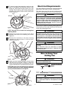
CEILING COVER
THREADED STUD
KNURLED KNOB
LOCKWASHERS (2)
Figure 12
CODE SWITCH
BATTERY COVER
REMOTE CONTROL
TRANSMITTER
BATTERY
SET
1
2
3
4
O
N
CODE SWITCH
SWITCH
LEVERS
1 2 3 4
ON
Figure 14
5. Secure the ceiling cover in place by sliding
lockwashers over the threaded studs and installing
the two knurled knobs (supplied). (Figure 12.)
Tighten the knurled knobs securely until the ceiling
cover fits snugly against the ceiling and the hole in
the ceiling cover is clear of the downrod. Your fan
is now wired to be turned on and off from the fan
switch.
To avoid possible fire or shock, make sure that the
electrical wires are completely inside the outlet box
and not pinched between the ceiling cover and the
ceiling.
WARNING
!
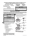
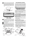
Installing Lamps and
Glass Globe
1. Carefully position one of the GU24 fluorescent
bulbs (supplied) into the light fitter socket, aligning
the two pins on the bottom of the bulb into the
socket holes. Twist the bulb clockwise,
approximately 1/16 turn, to engage the bulb pins
into the light socket holes.
2. Install the remaining three GU24 fluorescent bulbs
in the same manner.
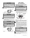
3. Place the glass bowl into the opening in the lower
housing assembly, aligning the three flat areas on
the top edge of the glass with the three raised
dimples on the lower housing assembly and turn
the glass bowl clockwise until it stops (Figure 13).
NOTE: periodically check that the glass bowl is
seated fully clockwise in the lower housing
assembly.
FLAT AREA
OF GLASS BOWL
RAISED DIMPLES OF
LIGHT KIT HOUSING
FLOURESCENT
LAMP PLUG (4)
Figure 13
U.L. Model No.: CF955
7