


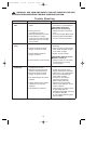
6
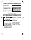
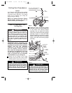
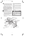
4. Remove the hanger ball by loosening
the setscrew in the hanger ball until the
ball falls freely down the downrod
(Figure 3). Remove the pin from the
downrod, then remove the hanger ball.
Retain the pin and hanger ball for
reinstallation in step 10.
PIN
HANGER
BALL
SETSCREW
DOWNROD
Figure 3
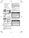
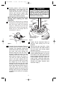
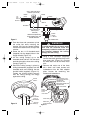
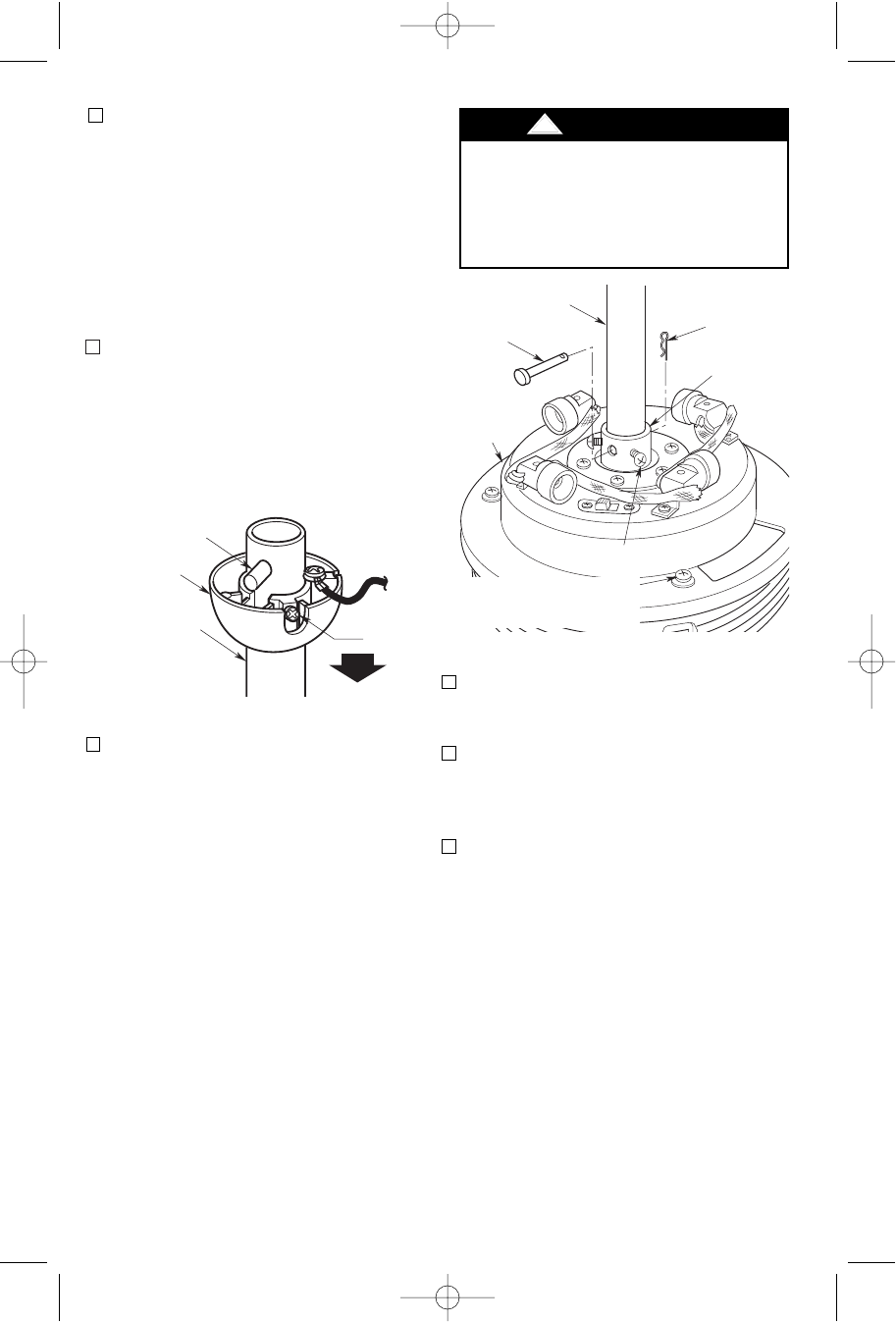
HAIRPIN
CLIP
MOTOR
COUPLING
SETSCREW (2)
CLEVIS
PIN
DOWNROD
MOTOR AND
HOUSING
UPLIGHT
ASSEMBLY
REMOVE THREE M4 x 12mm
PAN HEAD SCREWS AND
RUBBER WASHERS
Figure 4
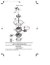
5. Unscrew the two setscrews (Figure 4)
until they clear the inside of the motor
coupling. Then separate, untwist and
unkink the three 80” motor leads. Route
the motor lead wires through the
downrod. Align the clevis pin holes in
the downrod with the holes in the motor
coupling. Install the clevis pin and
secure with the hairpin clip (Figure 4).
The clevis pin must go through the
holes in the motor coupling and the
holes in the downrod. Be sure to push
the straight leg of the hairpin clip
through the hole near the end of the
clevis pin until the curved portion of the
hairpin clip snaps around the clevis pin.
The hairpin clip must be properly
installed to prevent the clevis pin from
working loose. Pull up on the downrod
to make sure the clevis pin is properly
installed.
!
WARNING
It is critical that the clevis pin in the motor
coupling is properly installed and the
setscrews securely tightened. Failure to
verify that the pin and setscrews are
properly installed (as shown in Figure 4)
could result in the fan falling.
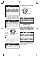
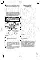
3. Carefully position a M5 x 16mm oval
head screw in one flange hole and
loosely tighten the screw (Figure 2).
Install the second screw in the same
manner and securely tighten both
screws. Repeat steps 2 and 3 for the
remaining four blade assemblies.
NOTE: Take care not to scratch the fan
housing when installing the blade
assemblies.
6. Tighten the two setscrews (Figure 4)
securely while pulling up on the
downrod.
7. Remove and retain three M4 x 12mm
pan head screws and rubber washers
from the motor and housing uplight
assembly (Figure 4).
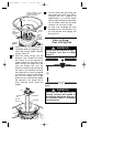
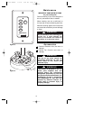
8. Place the upper glass on the motor and
housing uplight assembly. Line up the
three holes in the upper glass with the
three threaded holes in the motor and
housing uplight assembly (Figure 5).
Install an M4 x 12mm pan head screw
and rubber washer in each of the holes
(Screws and rubber washers were
removed in step 7).
BP7309 BANFF 1/5/06 9:59 AM Page 6