


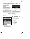
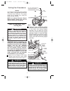
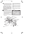
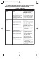
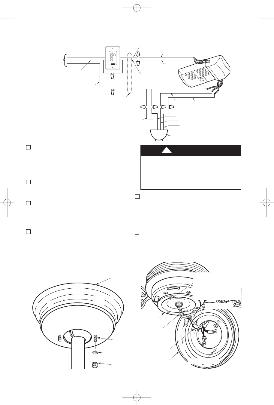
To avoid possible fire or shock, make
sure that the electrical wires are
completely inside the outlet box and
not pinched between the ceiling
canopy and the ceiling.
!
WARNING
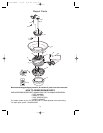
SW101 FAN/LIGHT WALL
CONTROL (SUPPLIED)
BLACK
BLACK
WHITE
RED
BLACK
WHITE
HANGER BALL
GREEN WIRE (GROUND)
FROM HANGER BALL AND
HANGER BRACKET
TWO-CONDUCTOR
CABLE (WITH
GROUND)
BLACK
(HOT)
WHITE
GROUND
TO
120-
VOLT
SUPPLY
WHITE
BLUE
WHITE
BLUE
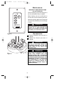
EMERSON
®
HI
MED
LOW
FAN OFF
LIGHT
ONOFF
Figure 11
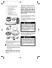
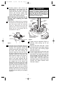
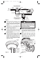
3. Push the wires and connectors up into
the outlet box while inserting the
receiver fully into the hanger bracket.
Position the antenna wire on top of the
receiver.
4. Screw the two 1-1/4” threaded studs
(supplied) into the tapped holes in the
hanger bracket (Figure 10).
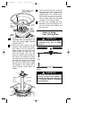
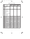
5. Lift the ceiling canopy up to the
threaded studs and turn until the studs
protrude through the holes in the ceiling
canopy (Figure 12).
6. Secure the ceiling canopy in place by
sliding lockwashers (supplied) over the
threaded studs and installing the two
knurled knobs (supplied) (Figure 12).
Tighten the knurled knobs securely
until the ceiling canopy fits snugly
against the ceiling.
1-1/4"
THREADED
STUD (2)
CEILING
CANOPY
KNURLED
KNOB (2)
LOCKWASHER
(2)
Figure 12
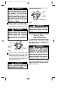
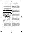
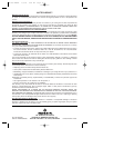
BLACK WIRE
BLUE WIRE
FITTER
ADAPTER
PLATE
DOWNLIGHT
FITTER ASSEMBLY
WHITE WIRES
REMOVE ONE M4 x 8mm
OVAL HEAD SCREW AND
LOCKWASHER.
LOOSEN THE TWO
REMAINING SCREWS AND
LOCKWASHERS.
KEYHOLE SLOTS
Figure 13
7. Using a wire connector (supplied),
connect the black light fitter wire to the
blue motor wire (Figure 13). Connect
the white fitter wire to the white motor
wire.
8. Remove and retain one of the three
M4 x 8mm oval head screws and
lockwashers from the fitter adapter
plate. Loosen the remaining two
screws and lockwashers.
10
BP7309 BANFF 1/5/06 9:59 AM Page 10