8
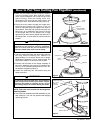
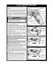
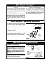
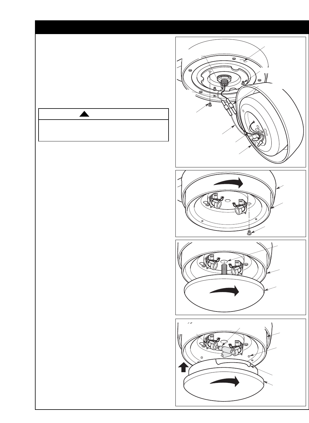
4 Position the light kit assembly onto the fan motor
assembly, safely tucking all wires and connectors
inside the light kit assembly.
5. Engage the two key slots on the light kit assembly
with two loosened screws in motor housing
assembly. Rotate the light kit assembly clockwise
to engage the two screws into both slots and
tighten securely. Install the previously removed
screw into the remaining hole of the light kit
assembly, attaching it to the fan motor assembly
securely (Figure 12).
6. If no light kit is to be used, screw the light kit
cover plate into the center hole of the light kit
assembly. Rotate the light kit cover plate
clockwise until fully installed (Figure 13).
CAUTION: To avoid risk of burns or other injury,
assure power is off before attempting to install or
replace the 50-watt (max.) mini-candelabra base
halogen lamps. Halogen lamps are very hot and
can cause burns. Allow the lamps to cool
sufficiently before handling.
CAUTION: To not touch 50-watt (max.) mini-
candelabra base halogen lamps with bare hands.
Fingerprints may result in shorter lamp life.
Remove fingerprints with alcohol.
7. If light kit assembly is to be used as a down
light, screw in two 50-watt (maximum) mini-
candelabra base halogen lamps (supplied) into the
light kit assembly light sockets (Figure 14).
8. Place the light kit glass shade into the light kit
assembly, aligning the three flat areas on the top
flange of the glass shade with the three raised
studs in the light kit assembly. Then turn the glass
shade clockwise until it stops and is secure
(Figure 14).
NOTE: Periodically check that the glass bowl is
seated fully clockwise in the light kit assembly.
9. Installation of your ceiling fan is now complete.
Proceed with installation of the wall control.
Lower Light Kit Assembly
REMOVE & RETAIN
ONE SCREW FROM
MOTOR HOUSING
LIGHT KIT WHITE WIRE
LIGHT KIT BLACK WIRE
WIRE CONNECTORS
MOTOR
HOUSING
WHITE WIRE
LIGHT KIT ASSEMBLY
LOOSEN TWO SCREWS
MOTOR HOUSING
ASSEMBLY
MOTOR HOUSING
BLACK WIRE
Figure 11
REINSTALL SCREW
LIGHT KIT
ASSEMBLY
MOTOR
HOUSING
ASSEMBLY
Figure 12
LIGHT KIT
COVER PLATE
LIGHT KIT
ASSEMBLY
LIGHT KIT
ASSEMBLY
CENTER HOLE
Figure 13
LIGHT KIT
ASSEMBLY
RAISED
STUDS (3)
LIGHT KIT
GLASS SHADE
GLASS SHADE
FLAT AREAS (3)
LIGHT KIT
SOCKETS (2)
50-WATT BASE
LAMPS (2)
Figure 14
ETL Model No.: CF550
Please call Emerson technical support at
1-800-654-3545 if you have any questions
about installation and operation of this ceiling fan.
Make sure all wires and connectors are tucked under
the light kit assembly and not pinched between light
kit assembly and fan motor assembly.
WARNING
!
1. With the fan assembly safely installed on the
mounting bracket, install the lower light kit as
follows.
2. Remove one screw (retain for future use) and
loosen the two other screws in the motor housing
for installation of the light kit assembly (Figure 11).
3. Connect the white wire from the ceiling fan
assembly to the white wire of the light kit assembly
(Figure 11). Connect the black wire from the ceiling
fan assembly to the black wire of the light kit
assembly.


