


1. Restore electrical power to the outlet box by turning
the electricity on at the main fuse box.
2. Check the operation of the fan by gently pulling on
the 4-position speed control switch pull chain. The
operating sequence is as follows:
THREE-SPEED
1st Pull—HIGH 3rd Pull—Low
2nd Pull—Medium 4th Pull—OFF
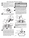
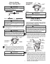
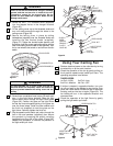
3. If airflow is desired in opposite direction, turn your
fan off and wait for the blades to stop turning, then
press the rocker switch located on top of the motor
housing, and turn the fan on again (Figure 23). The
fan blades will turn in the opposite direction and
reverse airflow.
4. Check the operation of the light fixture by gently
pulling the light switch pull chain.
9
Using Your Ceiling Fan
LIGHT SWITCH
PULL CHAIN
SPEED CONTROL
SWITCH PULL
CHAIN
REVERSING SWITCH
TOP OF
HOUSING
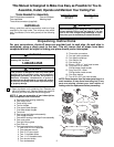
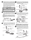
3. Screw the two 1-1/4” threaded studs (supplied)
into the tapped holes in the hanger bracket
(Figure 20).
4. Lift the ceiling cover up to the threaded studs and
turn until studs protrude through the holes in the
ceiling cover (Figure 20).
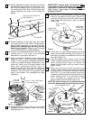
5. Secure the ceiling cover in place by sliding
lockwashers (supplied) over the threaded studs and
installing the two knurled knobs (supplied).
(Figure 21.) Tighten the knurled knobs securely until
the ceiling cover fits snugly against the ceiling and the
hole in the ceiling cover is clear of the downrod. Your
fan is now wired to be turned on and off from the fan
switch.
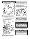
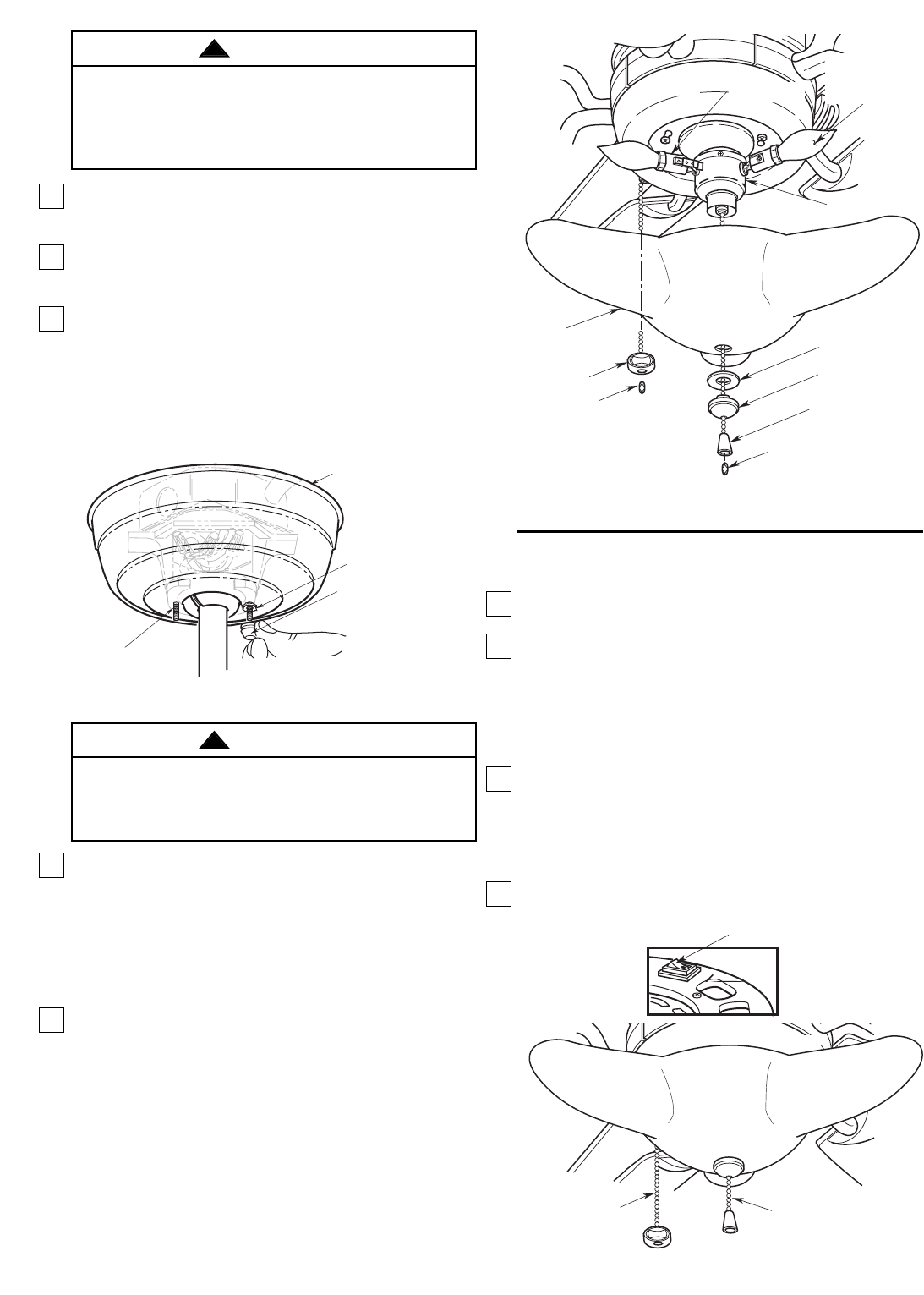
6. Screw three candelabra base lamps (60-watt each
max.) in the light fixture sockets. Pass the light
fixture switch chain through the light fixture glass
(Figure 22). Position the glass on the light fixture
so that the three elongated points of the glass are
over the three lamps. Install the fiber washer and
the finial nut (supplied) to hold the glass on the
light fixture. Securely tighten the finial nut.
7. Slip the speed control switch pull chain through the
hole in the oval pendant (supplied), then secure
the pendant by snapping the plastic coupling
(supplied) onto the end of the chain (Figure 22).
Repeat this procedure to connect the pendant to
the light switch pull chain.
CEILING COVER
LOCKWASHERS (2)
KNURLED KNOBS (2)
1-1/4"
THREADED
STUDS (2)
Figure 21
FIBER WASHER
FINIAL NUT
LIGHT FIXTURE
PENDANT
PLASTIC
COUPLING
GLASS
SPEED
CONTROL
PENDANT
PLASTIC
COUPLING
LIGHT FIXURE
SOCKET (3)
60-WATT
CANDELABRA
BASE LAMP (3)
Figure 22
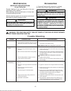
To avoid possible fire or shock, make sure that the
electrical wires are completely inside the outlet box
and not pinched between the ceiling cover and the
ceiling.
WARNING
!
Check to see that all connections are tight, including
ground, and that no bare wire is visible at the wire
connectors, except for the ground wire. Do not
operate fan until blades are in place. Noise and fan
damage could result.
WARNING
!
Figure 23