


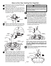
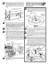
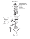
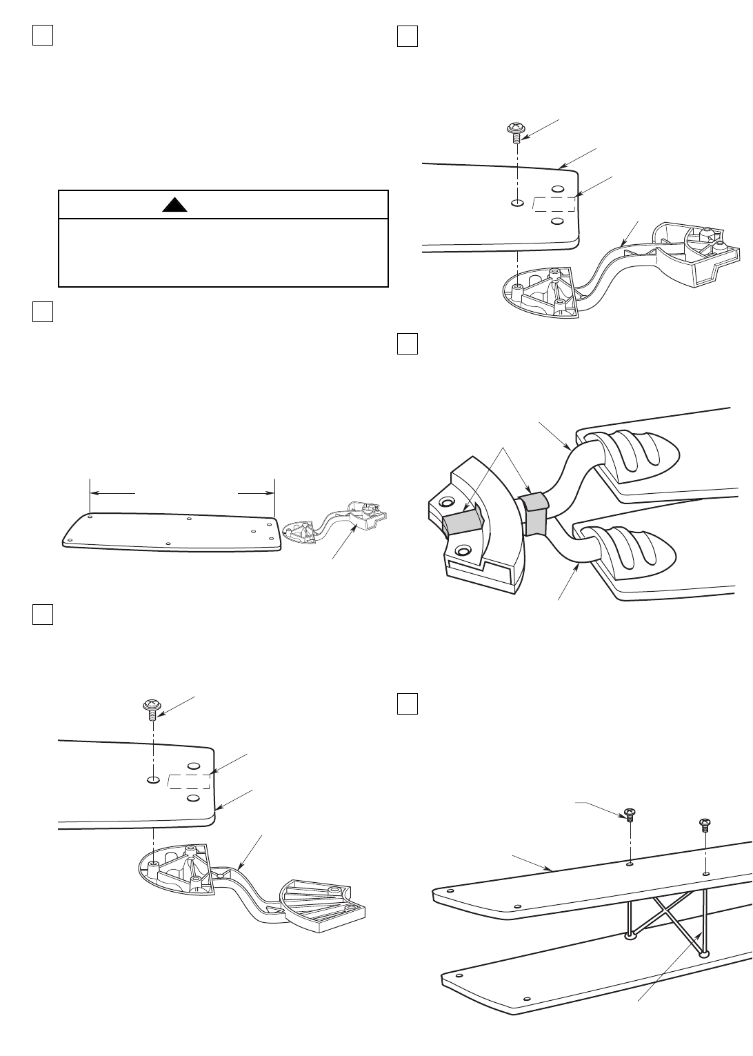
11. Use three 10-32 x 8mm slotted Phillips button
head screws to secure the fan blade to the lower
blade flange (Figure 7). (Refer to IMPORTANT
note above step 10.) Repeat the procedure for the
remaining four lower blades.
12. Position the lower blade flange on the upper
blade flange (Figure 8) and secure the flanges to
each other using several strips of masking tape.
(The masking tape will be removed later.)
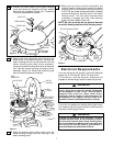
IMPORTANT: In Steps 13, 14, and 15, DO NOT use
electric screwdrivers to install the struts.
HAND TIGHTEN ONLY and avoid excessive torque.
13. Slightly separate the upper and lower fan blades
and carefully seat the strut into the center holes of
the fan blades (Figure 9). Secure the strut by
installing two 6-32 x 6mm Phillips button head
screws (supplied). Be careful not to scratch the
blades.
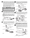
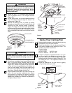
8. Reinstall the hanger ball on the downrod (Figure 4)
as follows. Route the motor leads through the
hanger ball and slide the hanger ball over the
downrod. Install the pin through the holes at the top
of the downrod and slide the hanger ball up the
downrod, aligning the ball so the pin in captured in
the groove in the top of the hanger ball. Pull the
hanger ball up tight against the pin and securely
tighten the setscrew in the hanger ball. A loose
setscrew could create fan wobble.
9. The fan comes with blue, black and white leads
that are 80-inches long. Before installing the fan,
measure up approximately 6 to 9-inches above top
of hanger ball/downrod assembly. Cut off excess
leads and strip back insulation 1/2-inch from end of
leads.
IMPORTANT: When installing the fan blades on
the blade flanges, be sure the short side of the fan
blade is oriented with the blade flange as shown
in Figure 5.
10. Use three 10-32 x 8mm Phillips button head
screws to secure the fan blade to the upper blade
flange (Figure 6). (Refer to IMPORTANT note
above.) Repeat the procedure for the remaining
four upper blades.
5
SHORT SIDE OF
FAN BLADE
BLADE FLANGE
Figure 5
UPPER BLADE FLANGE
FAN BLADE
10-32 x 8mm PHILLIPS BUTTON
HEAD SCREWS (3)
LABEL LOCATED ON
FAR SIDE
Figure 6
LOWER BLADE FLANGE
FAN BLADE
10-32 x 8mm PHILLIPS BUTTON
HEAD SCREWS (3)
LABEL LOCATED ON
FAR SIDE
Figure 7
UPPER BLADE FLANGE
LOWER BLADE FLANGE
MASKING TAPE
Figure 8
FAN BLADE
6-32 X 6mm PHILLIPS
BUTTON HEAD SCREWS (2)
STRUT
Figure 9
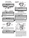
It is critical that the pin in the hanger ball is properly
installed and the setscrews securely tightened.
Failure to verify that the pin and setscrews are
properly installed could result in the fan falling.
WARNING
!