


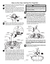
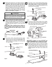
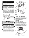
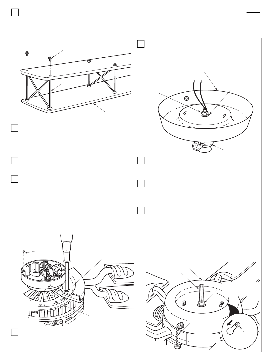
14. Slightly separate the upper and lower fan blades
and carefully seat the strut into the holes in the
end of the fan blades (Figure 10). Secure the strut
by installing two 6-32 x 6mm Phillips button head
screws (supplied). Be careful not to scratch the
blades.
15. Grasp the blades and turn them over, then install
the remaining four 6-32 x 6mm Phillips button
head screws (supplied) to secure the struts.
Remove the masking tape securing the two
blade flanges together. Repeat steps 12 through
15 for the remaining four blade assemblies.
16. Use the 10 round recessed holes in the motor hub
marked with “5” and install the five blade
assemblies in accordance with step 17.
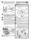
17. Attach one blade assembly to the motor hub
using two 10-32 x 1” oval head screws (supplied)
(Figure 11). Do not tighten completely at this time.
Install four remaining blade assemblies in the
same way. Gently snug all flange screws to the
motor hub, working around the hub in a
clockwise sequence. Next, securely tighten all
flange screws, again working in a clockwise
sequence. Failure to follow this procedure could
result in fan wobble. This completes the blade
installation.
18. Partially screw two 8-32 x 3/8” pan head screws
(supplied) into the threaded holes in the switch
housing (Figure 11).
IMPORTANT: Perform steps 19 through 23 ONLY
if you want to install your ceiling fan without the
light fixture. If you want to install your fan with the
light fixture, omit steps 19 through 23 and
proceed to step 24.
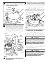
19. Remove the nut and lockwasher securing the light
fixture to the switch housing cover (Figure 12).
Unscrew the light fixture from the switch housing
cover. Retain the light fixture in case you want to
install it later.
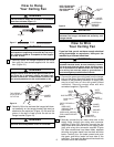
20. Screw the 2-1/4” pipe nipple (supplied) several full
turns into the switch housing cover (Figure 13).
Reinstall and tighten the lockwasher and nut onto
the nipple (Figure 13).
21. Pass the speed control switch chain from the
switch housing through the chain bushing in the
switch housing cover (Figure 13). Attach the
speed control pendant to the pull chain using a
plastic coupler.
22. Make sure all wires and wire connectors are
inside the switch housing, then position the switch
housing cover on the switch housing so that the
two 8-32 x 3/8” pan head screws (previously
installed) protrude through the keyhole slots in the
switch housing cover. Turn the switch housing
cover clockwise to engage the slots, then
securely tighten the two screws (Figure 13).
NOTE: Be sure the wires are not pinched between
the switch housing and the switch housing cover.
6
FAN BLADE
6-32 x 6mm PHILLIPS BUTTON
HEAD SCREWS (2)
STRUT
Figure 10
SWITCH HOUSING
COVER
REMOVE AND
RETAIN THIS NUT
REMOVE AND
RETAIN THIS
LOCKWASHER
LIGHT FIXTURE
Figure 12
SWITCH HOUSING COVER
2-1/4" PIPE
NIPPLE
TIGHTEN TWO
8-32 x 3/8"
PAN HEAD
SCREWS
REINSTALL
LOCKWASHER AND
NUT
SPEED CONTROL
SWITCH CHAIN
SPEED CONTROL
PENDANT
Figure 13
10-32 x 1" OVAL HEAD SCREW
(2 per blade assembly)
MOTOR HUB
8-32 x 3/8"
PAN HEAD
SCREWS (2)
SWITCH
HOUSING
Figure 11