


6
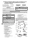
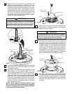
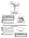
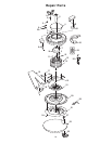
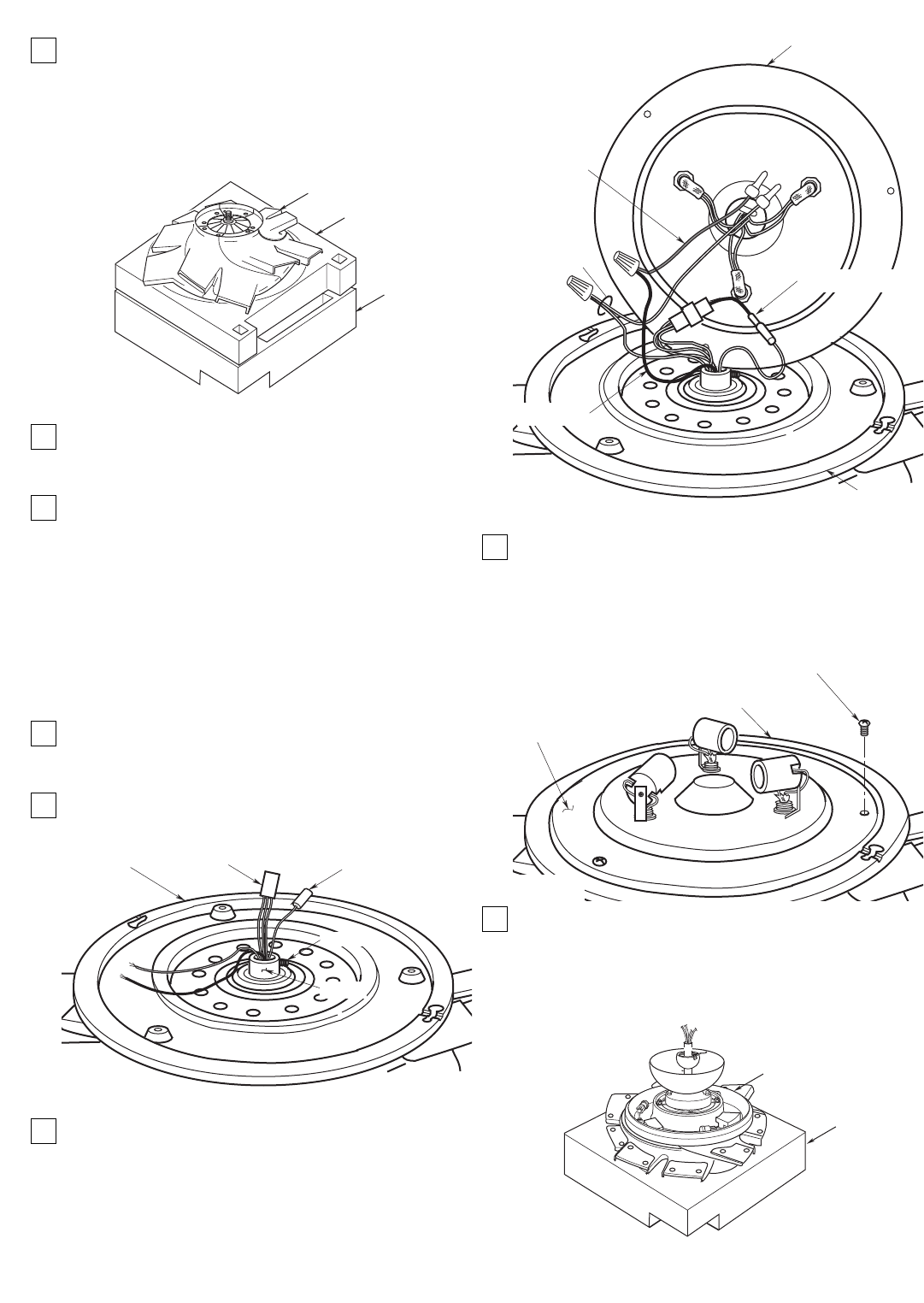
12. Position the center styrofoam section on the
upper section, and then position the fan motor
and housing on the center section so that the
bottom of the motor is facing you (Figure 5). The
styrofoam sections will hold the assembly while
you perform the following steps.
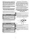
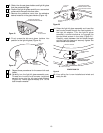
13.Using the 3/16” setscrew wrench (supplied),
loosen the setscrew in the collar of the light kit
adapter assembly (Figure 6).
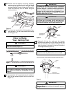
14.Pass the connectors and wires from the motor
shaft through the light kit adapter collar (Figure 7)
in the following sequence:
CENTER
STYROFOAM
SECTION
FAN MOTOR AND
HOUSING ASSEMBLY
UPPER
STYROFOAM
SECTION
Figure 5
a. First, pass the four-pin connector through the
collar;
b. Next, pass the single-pin connector through the
collar;
c. Then pass the white and blue wires through the
collar.
15.Screw the light kit adapter tightly onto the motor
shaft (Figure 6), then tighten the setscrew in the
collar.
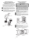
16.Securely connect the jumper assembly (supplied)
connectors to the four-pin connector and the one-
pin connector from the motor shaft (Figure 7).
17. Securely connect the black wire from the light kit
plate assembly to the blue wire from the motor
shaft using a wire connector (supplied) (Figure
7). Connect the white wire from the plate
assembly to the white wire from the motor shaft
using a wire connector (supplied).
SINGLE-PIN
CONNECTOR
SETSCREW
COLLAR
FOUR-PIN
CONNECTOR
LIGHT KIT
ADAPTER
Figure 6
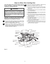
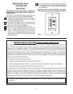
18. Secure the light kit plate assembly to the light kit
adapter by threading three 8-32 x 3/8” phillips
head screws (supplied) into the threaded holes in
the adapter assembly. (Figure 8).
NOTE: Do not pinch wires between the light kit
plate assembly and the adapter assembly.
19. Lift the fan assembly from the styrofoam and
remove the center styrofoam section. Turn the fan
assembly over and carefully position it on the
upper styrofoam section so that the hanger
ball/downrod assembly is at the top (Figure 9).
LIGHT KIT
ADAPTER
LIGHT KIT PLATE
ASSEMBLY
BLUE WIRE
BLACK WIRE
WHITE
WIRES
JUMPER ASSEMBLY
Figure 7
8-32 x 3/8" PHILLIPS
HEAD SCREW (3)
LIGHT KIT ADAPTER
LIGHT KIT
PLATE ASSEMBLY
Figure 8
UPPER
STYROFOAM
SECTION
FAN MOTOR AND
HOUSING ASSEMBLY
Figure 9