


5
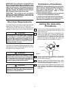
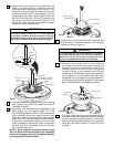
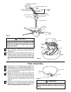
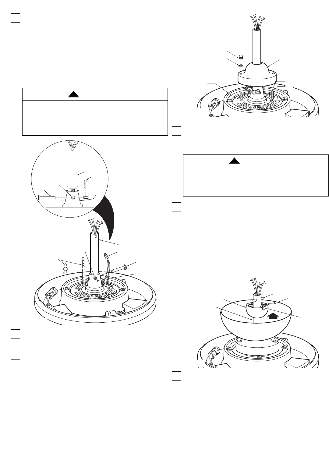
6. Align the clevis pin holes in the downrod with the
holes in the motor coupling. Install the clevis pin
and secure with the hairpin clip (Figure 2). The
clevis pin must go through the holes in the motor
coupling and the holes in the downrod. Push the
straight leg of the hairpin clip through the hole near
the end of the clevis pin until the curved portion of
the hairpin clip snaps around the clevis pin. The
hairpin clip must be properly installed to prevent
the clevis pin from working loose.
7. Install the setscrew (supplied) in the motor coupling
and tighten using the 5/32” setscrew wrench
(supplied) (Figure 2).
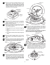
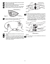
8. Screw two 1-1/4” threaded studs (supplied) into the
motor (Figure 3). Leave approximately 7/8” of the
stud extending above the motor. Coil the wires and
wire connectors around the motor coupling, then
slide the coupling cover over the downrod and
rotate the cover until the threaded studs protrude.
Install two lockwashers (supplied) and knurled
knobs (supplied) to secure the cover to the motor.
All wires and wire connectors must be enclosed
under the coupling cover.
NOTE: Lightly snug the knurled knobs and make
sure the wires and wire connectors are completely
inside the coupling cover and not pinched between
the coupling cover and the motor.
SETSCREW
CLEVIS PIN
MOTOR
COUPLING
DOWNROD
HAIRPIN
CLIP
MOTOR COUPLING
HAIRPIN
CLIP
CLEVIS
PIN
DOWNROD
CONNECT YELLOW WIRES
USING WIRE CONNECTOR
SETSCREW
CLEVIS
PIN
Figure 2
It is critical that the clevis pin in the motor coupling
is properly installed and the setscrew securely
tightened. Failure to verify that the pin and setscrew
are properly installed could result in the fan falling.
WARNING
!
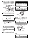
9. Position the ceiling cover over the downrod. Be
sure the cover is oriented correctly, with the large
opening at the top (Figure 4).
10. Reinstall the hanger ball on the downrod
as follows. Route the motor leads through the
hanger ball and slide the hanger ball over the
downrod (Figure 4). Install the pin through the
holes at the top of the downrod and slide the
hanger ball up the downrod, aligning the ball so the
pin is captured in the groove in the top of the
hanger ball. Pull the hanger ball up tight against the
pin and securely tighten the setscrew in the hanger
ball. A loose setscrew could create fan wobble.
11. The blue, black, white, and yellow leads exiting
the downrod are 80-inches long. Before installing
the fan, measure up approximately 6 to 9-inches
above the ball/downrod assembly. Cut off excess
leads and strip back insulation 1/2-inch from end
of leads.
CEILING COVER
SETSCREW
PIN
HANGER BALL
DOWNROD
Figure 4
It is critical that the pin in the hanger ball is properly
installed and the setscrew securely tightened.
Failure to verify that the pin and setscrew are
properly installed could result in the fan falling.
WARNING
!
KNURLED KNOB
1-1/4" THREADED
STUD
MOTOR
COUPLING COVER
7/8"
LOCKWASHER
Figure 3