


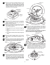
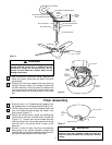

1. Position the fan motor and housing assembly in the
lower styrofoam packing so that the top for the
motor is facing you.
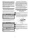
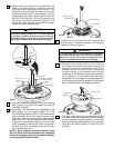
2. Obtain the hanger ball/downrod assembly and
remove the hanger ball by loosening the setscrew
in the hanger ball until the ball falls freely down the
downrod (Figure 1). Remove the pin from the
downrod, then remove the hanger ball. Retain the
pin and hanger ball for reinstallation in Step 11.
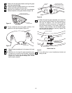
3. Using a wire connector (supplied), connect the
yellow uplight lead (supplied) to the yellow wire
from the motor (Figure 2).
4. Separate, untwist and unkink the three black, white
and blue motor wires and the yellow uplight lead.
Route these wires through the downrod.
5. Fold the wires from the downrod into the slot in the
motor coupling. Then slide the downrod down the
wires and seat the downrod in the motor coupling
(Figure 2).
HANGER BALL
PIN
DOWNROD
SETSCREW
Figure 1
If your fan is to replace an existing ceiling light fixture,
turn electricity off at the main fuse box at this time
and remove the existing light fixture.
Turning off wall switch is not sufficient. To avoid
possible electrical shock, be sure electricity is turned
off at the main fuse box before wiring. All wiring must
be in accordance with national and local codes and
the ceiling fan must be properly grounded as a
precaution against possible electrical shock.
WARNING
!
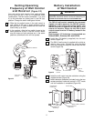
Your new ceiling fan will require a grounded electrical
supply line of 120 volts AC, 60 Hz, 15 amp circuit.
The outlet box must be securely anchored and
capable of withstanding a load of at least 50 pounds.
To reduce the risk of fire, electric shock, or personal
injury, mount fan to outlet box marked “Acceptable
for Fan Support”, and use screws supplied with
outlet box. Most outlet boxes commonly used for
support of light fixtures are not acceptable for fan
support and may need to be replaced. Consult a
qualified electrician if in doubt.
WARNING
!
Electrical Requirements
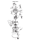
Ceiling Fan Assembly
Procedures
To avoid possible fire or shock, follow all wiring
instructions carefully. Any electrical work not
described in these instructions should be done or
approved by a licensed electrician.
WARNING
!
4
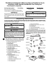
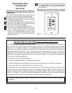
IMPORTANT: Your ceiling fan is supplied with an
SW116 Fan/Light Wall Control (transmitter) and a
remote control SW105 Receiver which mounts
under the ceiling cover. This system allows you to
regulate your ceiling fan speed, airflow direction,
and light intensity. An optional Emerson Electric
SR110 Remote Control may also be used.
IMPORTANT: Your ceiling fan will not function
properly and may be damaged, if used with any
wall dimmer switch or control other than the
Emerson controls listed above.
Preliminary Procedures
IMPORTANT: Before assembling your ceiling fan,
refer to sections “Setting Operating Frequency of
Wall Control and Receiver” and “Battery
Installation of Wall Control”, page 11. These
sections instruct you how to:
a. Set the operating frequency of the fan/light wall
control and the remote control receiver.
b. Install the fan/light wall control in the wall box.
You will then be ready to proceed with the
assembly and installation of your ceiling fan.