


6
UL Model No.: CF130
1. Carefully turn the partially assembled
ceiling fan right side up and place the
fan securely into the packing sytrofoam
in preparation for final assembly.
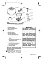
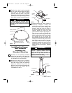
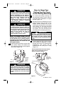
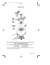
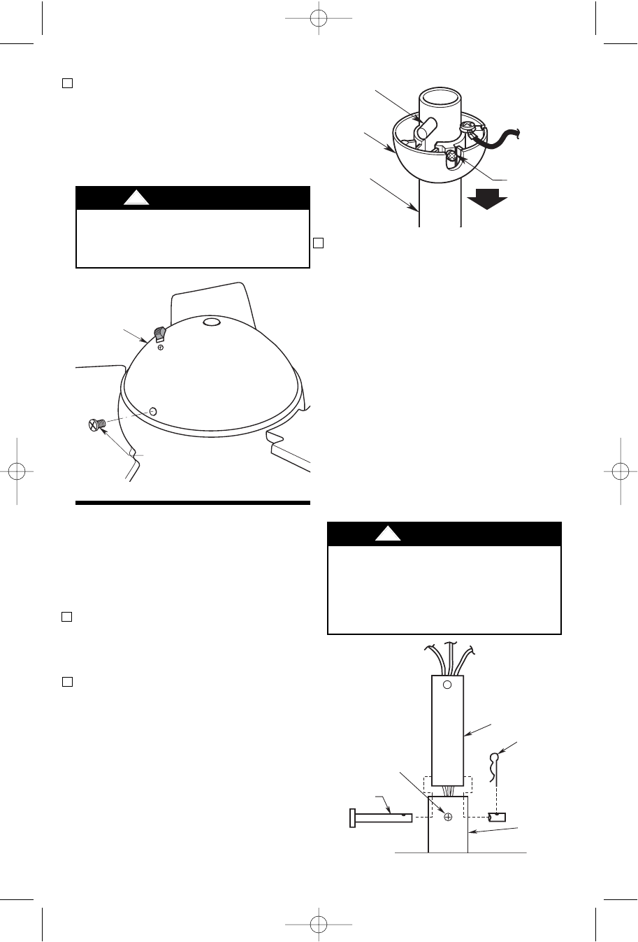
2. Remove the hanger ball by loosening
the setscrew in the hanger ball until the
ball falls freely down the downrod
(Figure 4). Remove the pin from the
downrod, then remove the hanger ball.
Retain the pin and hanger ball for
reinstallation in Step 7.
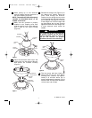
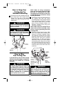
3. Loosen setscrew in motor coupler if
necessary. Separate, untwist and
unkink the three 42” motor leads. Route
the motor lead wires through the
downrod. Align the clevis pin holes in
the downrod with the holes in the motor
coupler. Install the clevis pin and
secure with the hairpin clip (Figure 5).
The clevis pin must go through the
holes in the motor coupler and the
holes in the downrod. Be sure to push
the straight leg of the hairpin clip
through the hole near the end of the
clevis pin until the curved portion of the
hairpin clip snaps around the clevis pin.
The hairpin clip must be properly
installed to prevent the clevis pin from
working loose. Pull on the downrod to
make sure the clevis pin is properly
installed.
PIN
HANGER
BALL
SETSCREW
DOWNROD
Figure 4
It is critical that the clevis pin in the motor
coupler is properly installed and the
setscrew securely tightened. Failure to
verify that the pin and setscrew are
properly installed (as shown in Figure 5)
could result in the fan falling.
!
WARNING
SETSCREW
CLEVIS PIN
MOTOR
COUPLING
DOWNROD
HAIRPIN
CLIP
DOWNROD
HAIRPIN
CLIP
MOTOR
COUPLING
SETSCREW (2)
CLEVIS PIN
Figure 5
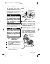
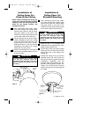
To avoid possible fire or shock, do not
pinch wires between the switch housing
assembly and the bracket switch housing
assembly.
!
WARNING
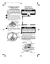
SWITCH HOUSING
ASSEMBLY
REINSTALL M4 x 8mm
FLAT HEAD SCREWS (3)
Figure 3
7. Position the switch housing assembly
on the switch housing plate and align
the holes in the switch housing
assembly with the holes in the plate.
Secure the switch housing assembly by
installing the three previously removed
M4 x 8mm flat head screws (Figure 3).
Installing the Hanger
Ball/ Downrod
Assembly for
Standard Mounting
BP7404 Tilo 12/16/09 4:06 PM Page 6