


6
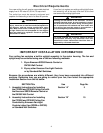
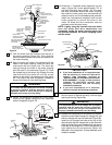
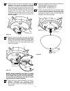
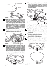
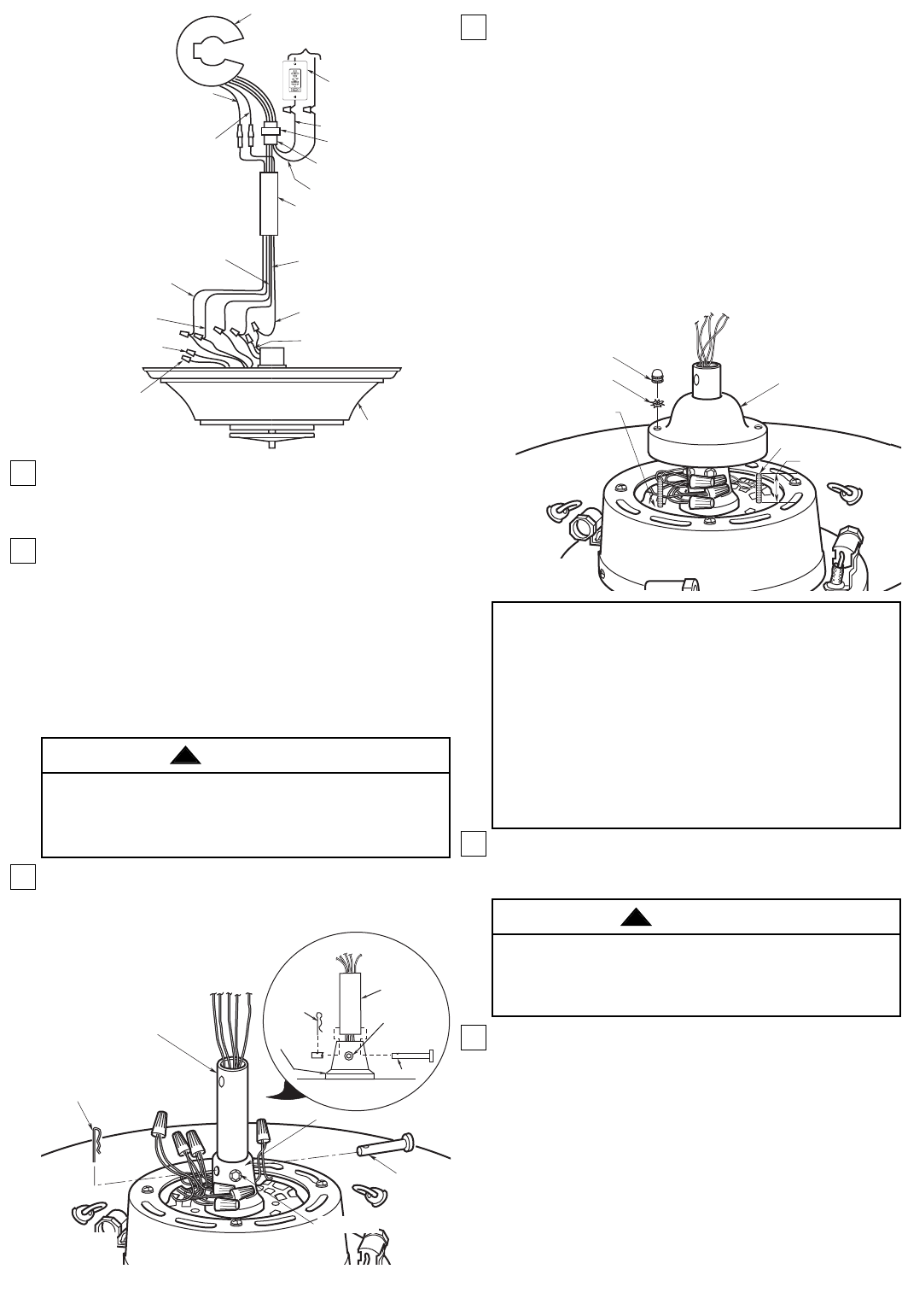
11. Fold the wires from the downrod into the slot in
the motor coupling (Figure 5A). Then slide the
downrod down the wires and seat the downrod in
the motor coupling.
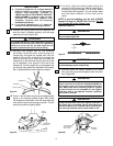
12. Align the clevis pin holes in the downrod with the
holes in the motor coupling. Install the clevis pin
and secure with the hairpin clip. The clevis pin
must go through the holes in the motor coupling
and the holes in the downrod (Figure 7A). Push
the straight leg of the hairpin clip through the hole
near the end of the clevis pin until the curved
portion of the hairpin clip snaps around the clevis
pin. The hairpin clip must be properly installed to
prevent the clevis pin from working loose.
13. Install the setscrew (supplied) in the motor
coupling and tighten using the 5/32” setscrew
wrench (supplied) (Figure 7A).
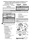
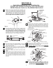
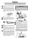
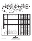
Off On
Up Down
Lights
Fan
Sleep
HANGER
PIPE
WHITE WIRE
BLACK WIRE
WIRING HARNESS
CONNECTOR
YELLOW WIRE
TO YELLOW
WIRE
BLUE WIRE TO
BLUE WIRE
SW375 RECEIVER
TO
120V SUPPLY
SW350
WALL CONTROL OR
ON/OFF WALL SWITCH
RECEIVER
CONNECTOR
BROWN WIRE
(FROM THE MOTOR)
TO BROWN WIRE
BLACK WIRE (NOT USED)
RED WIRE
(FROM THE
MOTOR) TO
RED WIRE
WHITE WIRE TO
WHITE WIRE
FAN HOUSING AND
SHADE ASSEMBLY
RED WIRE (FROM THE
REVERSING SWITCH)
(NOT USED)
BROWN WIRE (FROM
THE REVERSING
SWITCH) (NOT USED)
YELLOW WIRE
(FROM THE
MOTOR) TO
YELLOW WIRE
BLUE WIRE TO
BLUE WIRE
Figure 6A
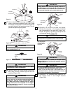
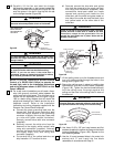
14. Screw two 1” threaded studs (supplied) into the
motor (Figure 8A). Leave approximately 7/8” of
the stud extending above motor. Coil the wires
and wire connectors around the motor coupling,
then slide the motor cover over the downrod and
rotate the cover until the threaded studs protrude.
Install two lockwashers (supplied) and knurled
knobs (supplied) to secure the cover to the
motor. All wires and wire connectors must be
enclosed under the motor cover.
NOTE: Lightly snug the knurled knob and make
sure the wires and wire connectors are
completely inside the motor coupling cover and
not pinched between the motor coupling cover
and the motor.
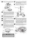
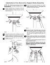
15. Position the ceiling cover over the downrod. Be
sure the cover is oriented correctly, with the large
opening at the top (Figure 9A).
16. Reinstall the hanger ball on the downrod as follows.
Route the motor leads through the hanger ball and
slide the hanger ball over the downrod (Figure 9A).
Install the pin through the holes at the top of the
downrod and slide the hanger ball up the downrod,
aligning the ball so the pin is captured in the groove
in the top of the hanger ball. Pull the hanger ball up
tight against the pin and securely tighten the
setscrew in the hanger ball. A loose setscrew could
create fan wobble.
It is critical that the clevis pin in the motor coupling
is properly installed and the setscrew securely
tightened. Failure to verify that the pin is properly
installed could result in the fan falling.
WARNING
!
IMPORTANT
A. If you have installed an 18” or longer downrod
and are planning to install the decorative
support rods assembly, proceed to
“INSTALLATION OF DECORATIVE SUPPORT
RODS ASSEMBLY” on page 14. After you have
installed the decorative support rods
assembly, continue with the following
installation procedures.
B. If you have installed the 4-1/2” downrod,
continue now with the following procedures.
DOWNROD
MOTOR COUPLING
CLEVIS
PIN
HAIRPIN
CLIP
SETSCREW
CLEVIS PIN
MOTOR
COUPLING
DOWNROD
HAIRPIN
CLIP
SETSCREW
Figure 7A
7/8"
1" THREADED STUD
MOTOR COVER
KNURLED KNOB
LOCKWASHER
MOTOR
Figure 8A
It is critical that the pin in the hanger ball is properly
installed and the setscrew securely tightened.
Failure to verify that the pin and setscrew are
properly installed could result in the fan falling.
WARNING
!