


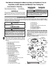
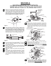
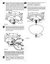
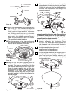
15. Carefully lift the fan and seat the hanger
ball/downrod assembly on the hanger bracket that
was just attached to the outlet box (Figure 9B). Be
sure the groove in the ball is lined up with the tab
on the hanger bracket (Figure 8B).
NOTE: If you are installing a SR330 Remote
Control or a SW350 Wall Control to operate the
fan and light, refer to the installation instructions
and wiring diagrams shown in SECTION A or this
Owner’s Manual.
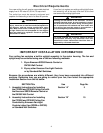
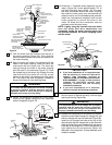
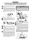
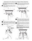
16. For a wall control installation you will need a three-
wire (with ground) conductor cable between the
ceiling and wall outlet boxes. This will allow you to
control the fan separately from the lights. Figure
10B is a basic wiring diagram that will control the
uplight and downlight on a switch and the fan on a
separate control. Refer to the installation
instructions and wiring diagrams supplied with the
Emerson Fan Control Owner’s Manual.
a. Connect the green grounding lead from the
hanger ball and the green grounding lead
from the hanger bracket to the grounding
conductor of supply (this may be a bare wire
or a wire with green colored insulation).
Securely connect wires with wire connector
(supplied).
b. Securely connect the white wire from the
downrod to the supply white (neutral) wire
using wire connector (supplied). Securely
connect the black wire from the downrod to
the supply black (hot) wire using wire
connector (supplied).
c. Cut terminal off of the yellow lead wire and
strip insulation 1/2” from end of wire.
d. Securely connect the blue wire and yellow
wire from the downrod to the supply red (hot)
wire using wire connector (supplied). After
connections have been made, turn leads
upward and carefully push leads into the
outlet box, with the white and green leads on
one side of the outlet box and the black, blue
and yellow leads on the other side of the
outlet box.
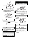
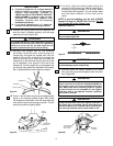
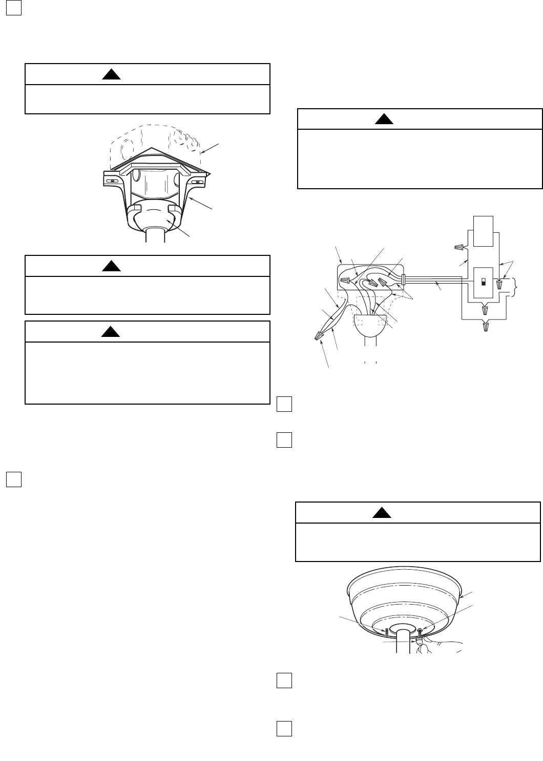
17. Lift the ceiling cover up to the threaded studs and
turn until studs protrude through the holes in the
ceiling cover (Figure 11B).
18. Secure the ceiling cover in place by installing two
lockwashers and two knurled knobs (supplied)
(Figure 11B). Tighten the knurled knobs securely
until the ceiling cover fits snugly against the
ceiling and the hole in the ceiling cover is clear of
the downrod.
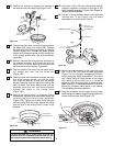
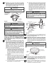
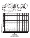
19. Use three 10-32 x 3/8” pan head screws and flat
washers (supplied) to secure the flange to the blade
(ordered separately) (Figure 12B). Repeat for the
four remaining blades.
20. Use the 10 round recessed holes in the motor hub
marked with “5” and install the five blade
assemblies in accordance with Step 21.
12
Failure to seat tab in groove could cause damage to
electrical wires and possible shock or fire hazard.
WARNING
!
OUTLET
BOX
HANGER
BRACKET
HANGER BALL/
DOWNROD ASSEMBLY
Figure 3
NOTE: CEILING COVER,
SUPPLY WIRES AND
FAN WIRES OMITTED
FOR CLARITY.
Figure 9B
To avoid possible fire or shock, do not pinch wires
between the hanger ball/downrod assembly and the
hanger bracket.
WARNING
!
BLACK
BLACK FAN WIRE
LISTED OUTLET BOX
LIGHT
CONTROL
GREEN WIRE
(GROUND)
FROM
HANGER
BRACKET
TO 120
VOLT
SUPPLY
WHITE
WHITE
GROUND
GROUND
GREEN WIRE (GROUND)
FROM HANGER BALL
LISTED WIRE
CONNECTOR (4)
GROUND
WIRE
WHT.
RED
BLACK
EMERSON
FAN
CONTROL
BLACK
(HOT)
YELLOW
BLUE
RED
Figure 10B
Check to see that all connections are tight, including
ground, and that no bare wire is visible at the wire
connectors, except for the ground wire. Do not
operate fan until blades are in place. Noise and fan
damage could result.
WARNING
!
To avoid possible fire or shock, make sure that the
electrical wires are completely inside the outlet box and
not pinched between the ceiling cover and the ceiling.
WARNING
!
1-1/4"
THREADED
STUD
LOCKWASHERS (2)
CEILING COVER
KNURLED KNOB
Figure 11B
To avoid possible electrical shock, be sure electricity
is turned off at the main fuse box before wiring.
NOTE: If you are not sure if the outlet box is
grounded, contact a licensed electrician for advice,
as it must be grounded for safe operation.
WARNING
!