


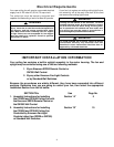
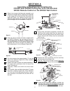
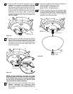
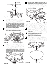
21. Attach one blade assembly to the motor hub using
two 10-32 x 5/8” oval head screws (supplied)
(Figure 13B). Do not tighten completely at this time.
Install remaining blade assemblies in the same
way. Gently snug all flange screws to the motor
hub, working around the hub in a clockwise
sequence. Next, securely tighten all flange screws,
again working in a clockwise sequence. Failure to
follow this procedure could result in fan wobble.
This completes the blade installation.
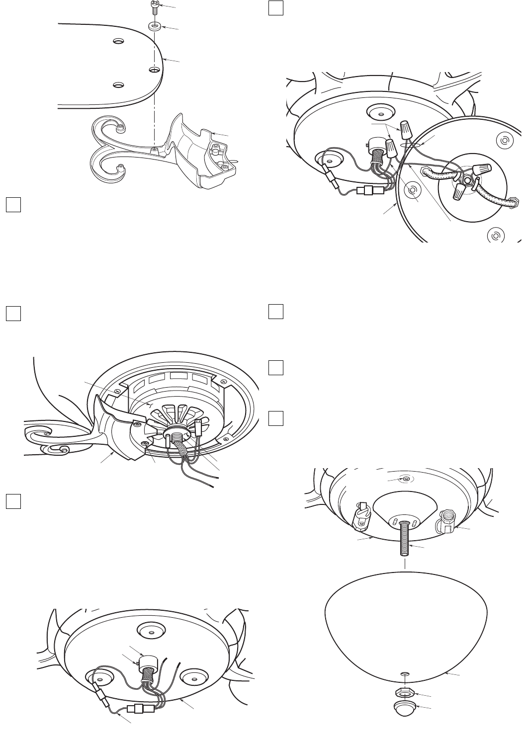
22. Pass the connectors and the wires from the motor
shaft through the washer (supplied) and position the
washer over the motor shaft (Figure 13B).
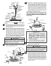
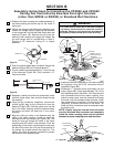
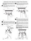
23. Using the 5/64” hex wrench (supplied), loosen the
setscrew in the collar on the light kit adapter
assembly. Then pass the connectors and the wires
from the motor shaft through the collar (Figure 14B).
Screw the adapter assembly onto the motor shaft
and then tighten the setscrew to secure the adapter
assembly to the motor shaft. Connect the
connectors from the motor shaft using the jumper
assembly (supplied). Verify that the connectors are
securely engaged.
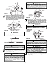
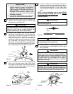
24. Securely connect the black wire from the light kit
plate assembly to the blue wire from the motor shaft
using a wire connector (supplied) (Figure 15B).
Connect the white wire from the plate assembly to
the white wire form the motor shaft using a wire
connector (supplied).
NOTE: When installing the light kit plate
assembly, position the wires and wire connectors
in the raised center portion of the plate assembly.
Do not pinch wires between the light kit plate
assembly and the adapter assembly.
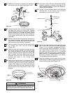
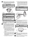
25. Secure the light kit plate assembly to the light kit
adapter assembly by threading three
5/32-32 x 3/16” phillips head screws (supplied) into
the threaded holes in the adapter assembly
(Figure 16B).
26. Install two candelabra base lamps in the sockets of
the light kit adapter plate (Figure 16B):
Model CF2600 - 15-Watt Maximum
Model CF2650 - 25-Watt Maximum
27. Position the glass shade over the threaded nipple in
the light kit plate assembly (Figure 16B). Seat the
glass shade evenly over the plate assembly and
securely install the hex nut and finial nut (supplied)
on the threaded nipple.
13
MOTOR HUB
BLADE FLANGE
10 - 32 x 5/8"
OVAL HEAD SCREW
(2 Per Blade Assembly)
WASHER
MOTOR
SHAFT
Figure 13B
BLADE
FLANGE
10-32 x 3/8"
PAN HEAD SCREW
FLAT WASHER
FAN BLADE
Figure 12B
LIGHT KIT
ADAPTER ASSEMBLY
JUMPER
ASSEMBLY
SETSCREW
COLLAR
Figure 14B
BLUE
WIRE
LIGHT KIT
PLATE ASSEMBLY
WIRE
CONNECTORS
BLACK
WIRE
WHITE WIRES
Figure 15B
LIGHT KIT
PLATE ASSEMBLY
SOCKET
THREADED NIPPLE
GLASS
SHADE,
LOWER
FINIAL
NUT
HEX NUT 1/8-27
5/32-32 x 3/16"
PHILLIPS HEAD
SCREW (3)
Figure 16B