


5
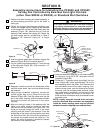
SECTION A
Assembly Instructions for Installing the
CF2600 and CF2650 Ceiling Fan with the Emerson
SR330 Remote Control or the SW350 Wall Control
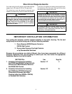
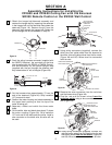
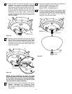
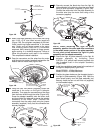
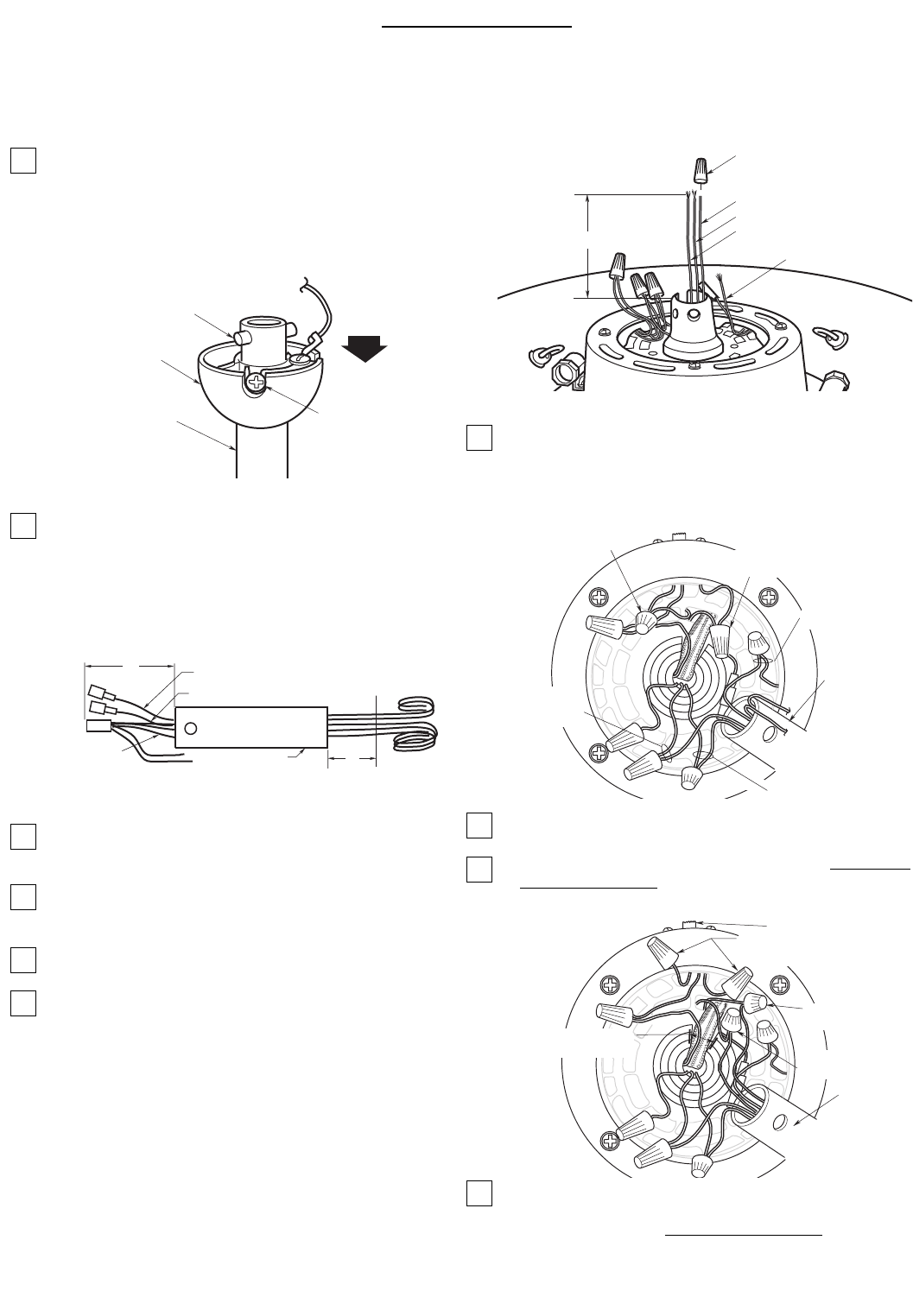
1. Obtain the hanger ball/downrod assembly and
remove the hanger ball by loosening the setscrew
in the hanger ball until the ball falls freely down the
downrod (Figure 1A). Remove the pin from the
downrod, then remove the hanger ball. Retain the
pin and hanger ball for reinstallation in Step 16.
2. Push the wiring harness connector (supplied with
the SW375 Receiver), the connector on the blue
wire (supplied with the SR330 or SW350 Control),
and the connector on the yellow uplight lead
(supplied with the fan) through the downrod until
they extend about 4” out of the pipe (Figure 2A).
3. Cut the harness wires approximately 3” from the
end of the downrod (Figure 2A). Strip insulation
1/2” from end of wires.
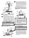
4. Position the motor housing and shade assembly in
the upper foam packing so that the top of the
motor is facing you.
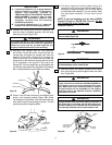
5. Separate, untwist and unkink the three motor
leads.
6. Cut the white, blue and black wires about 3” above
the motor coupling (Figure 3A). Strip insulation
1/2” from end of the white and blue wires. Install a
wire connector on the black wire; this wire will not
be used.
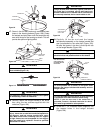
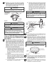
7. Using wiring connectors (supplied), connect the
white, blue and yellow wires from the downrod to
the white, blue and yellow wires from the fan motor
(Figure 4A and 6A). Wires must be connected
color-to-color.
8. Remove the wire connectors from the red wires
and the brown wires (Figure 4A).
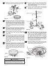
9. Cap the red and the brown wires from the
reversing switch using a wire connector on each
wire (Figure 5A).
10. Using wiring connectors (supplied), connect the
red and brown wires from the downrod to the red
and brown wires from the fan motor (Figure 5A
and 6A). Wires must be connected color-to-color.
HANGER BALL
PIN
DOWNROD
SETSCREW
Figure 1A
YELLOW WIRE
WHITE
WIRE
BLACK WIRE
BLUE WIRE
INSULATE BLACK
WIRE USING WIRE
CONNECTOR
3"
Figure 3A
REMOVE WIRE CONNECTOR
FROM RED WIRES
CONNECT
YELLOW WIRES
CONNECT
WHITE WIRES
CONNECT BLUE WIRES
DOWNROD
REMOVE WIRE CONNECTOR
FROM BROWN WIRES
Figure 4A
DOWNROD
SLOT IN MOTOR
COUPLING
CAP BROWN AND RED
USING WIRE CONNECTORS
CONNECT
RED WIRES
CONNECT
BROWN WIRES
REVERSING SWITCH
Figure 5A
4"
YELLOW UPLIGHT LEAD
BLUE WIRE
WIRING
HARNESS
DOWNROD
CUT HERE
3"
Figure 2A