


iii
7.4 Outdoor Air-Cooled Condensing Units . . . . . . . . . . . . . . . . . . . . . . . . . . . . . . . . . . . . . . . . . . 62
7.5 Centrifugal Air-Cooled Condensing Units . . . . . . . . . . . . . . . . . . . . . . . . . . . . . . . . . . . . . . . 67
7.5.1 Installing the Indoor Condensing Unit . . . . . . . . . . . . . . . . . . . . . . . . . . . . . . . . . . . . . . . . . . . 67
7.5.2 Ducting . . . . . . . . . . . . . . . . . . . . . . . . . . . . . . . . . . . . . . . . . . . . . . . . . . . . . . . . . . . . . . . . . . . . 68
7.6 Water and Glycol-Cooled Condensing Units. . . . . . . . . . . . . . . . . . . . . . . . . . . . . . . . . . . . . . 74
7.6.1 Piping Considerations . . . . . . . . . . . . . . . . . . . . . . . . . . . . . . . . . . . . . . . . . . . . . . . . . . . . . . . . 74
7.6.2 Condenser Water Requirements . . . . . . . . . . . . . . . . . . . . . . . . . . . . . . . . . . . . . . . . . . . . . . . . 74
7.6.3 Regulating Valve . . . . . . . . . . . . . . . . . . . . . . . . . . . . . . . . . . . . . . . . . . . . . . . . . . . . . . . . . . . . 74
7.6.4 Glycol Systems . . . . . . . . . . . . . . . . . . . . . . . . . . . . . . . . . . . . . . . . . . . . . . . . . . . . . . . . . . . . . . 75
8.0 R407C REFRIGERANT . . . . . . . . . . . . . . . . . . . . . . . . . . . . . . . . . . . . . . . . . . . . . . . . . . .79
8.1 Calculating Subcooling. . . . . . . . . . . . . . . . . . . . . . . . . . . . . . . . . . . . . . . . . . . . . . . . . . . . . . . 80
FIGURES
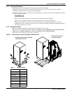
Figure 1 Removing the Liebert Challenger 3000 from skid . . . . . . . . . . . . . . . . . . . . . . . . . . . . . . . . . . . . . . 7
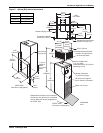
Figure 2 Upflow (BU) cabinet dimensions . . . . . . . . . . . . . . . . . . . . . . . . . . . . . . . . . . . . . . . . . . . . . . . . . . . . 8
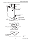
Figure 3 Downflow (BF) cabinet dimensions . . . . . . . . . . . . . . . . . . . . . . . . . . . . . . . . . . . . . . . . . . . . . . . . . . 9
Figure 4 Piping connections for air-cooled units - Downflow models . . . . . . . . . . . . . . . . . . . . . . . . . . . . . . 11
Figure 5 Piping connections for air-cooled units - Upflow models . . . . . . . . . . . . . . . . . . . . . . . . . . . . . . . . 12
Figure 6 Piping connections for split system fan coil units - Downflow models . . . . . . . . . . . . . . . . . . . . . 13
Figure 7 Piping connections for split system fan coil units - Upflow models . . . . . . . . . . . . . . . . . . . . . . . 14
Figure 8 Piping connections for water/glycol and GLYCOOL units - Downflow models . . . . . . . . . . . . . . 15
Figure 9 Piping connections for water/glycol and GLYCOOL units - Upflow models . . . . . . . . . . . . . . . . . 16
Figure 10 Piping connections for chilled water self-contained units - Downflow models . . . . . . . . . . . . . . . 17
Figure 11 Piping connections for chilled water self-contained units - Upflow models . . . . . . . . . . . . . . . . . 18
Figure 12 Electrical connections . . . . . . . . . . . . . . . . . . . . . . . . . . . . . . . . . . . . . . . . . . . . . . . . . . . . . . . . . . . . 20
Figure 13 Electrical field connections for Liebert iCOM
®
. . . . . . . . . . . . . . . . . . . . . . . . . . . . . . . . . . . . . . . . 21
Figure 14 Air-cooled condensers . . . . . . . . . . . . . . . . . . . . . . . . . . . . . . . . . . . . . . . . . . . . . . . . . . . . . . . . . . . . 25
Figure 15 General arrangement—Air-cooled models with fan speed control. . . . . . . . . . . . . . . . . . . . . . . . . 30
Figure 16 General arrangement—Air-cooled models with digital scroll and fan speed control . . . . . . . . . . 31
Figure 17 General arrangement—Air-cooled models with Liebert Lee-Temp
™
. . . . . . . . . . . . . . . . . . . . . . 34
Figure 18 General arrangement—Air-cooled models with digital scroll and Liebert Lee-Temp
™
. . . . . . . . 35
Figure 19 General arrangement—Water-cooled models with scroll compressor . . . . . . . . . . . . . . . . . . . . . . 37
Figure 20 General arrangement diagram—Water-cooled models with digital scroll . . . . . . . . . . . . . . . . . . 38
Figure 21 Johnson Controls valve adjustment. . . . . . . . . . . . . . . . . . . . . . . . . . . . . . . . . . . . . . . . . . . . . . . . . 39
Figure 22 Metrex Valve adjustment . . . . . . . . . . . . . . . . . . . . . . . . . . . . . . . . . . . . . . . . . . . . . . . . . . . . . . . . . 40
Figure 23 Drycoolers and pump packages . . . . . . . . . . . . . . . . . . . . . . . . . . . . . . . . . . . . . . . . . . . . . . . . . . . . 48
Figure 24 Pump packages—expansion tank . . . . . . . . . . . . . . . . . . . . . . . . . . . . . . . . . . . . . . . . . . . . . . . . . . 49
Figure 25 General arrangement—Glycol-cooled models with scroll compressor . . . . . . . . . . . . . . . . . . . . . . 50
Figure 26 General arrangement—Glycol-cooled models with digital scroll . . . . . . . . . . . . . . . . . . . . . . . . . . 51
Figure 27 General arrangement—GLYCOOL models with scroll compressor. . . . . . . . . . . . . . . . . . . . . . . . 52
Figure 28 General arrangement—GLYCOOL models with digital scroll compressor. . . . . . . . . . . . . . . . . . 53
Figure 29 Chilled water general arrangement - Upflow (BU). . . . . . . . . . . . . . . . . . . . . . . . . . . . . . . . . . . . . 55
Figure 30 Chilled water general arrangement - Downflow (BF) models . . . . . . . . . . . . . . . . . . . . . . . . . . . . 56
Figure 31 Refrigerant piping diagram . . . . . . . . . . . . . . . . . . . . . . . . . . . . . . . . . . . . . . . . . . . . . . . . . . . . . . . 60
Figure 32 Outdoor air-cooled condensing unit—horizontal air discharge models . . . . . . . . . . . . . . . . . . . . . 62
Figure 33 Outdoor air-cooled condensing unit—top air discharge models . . . . . . . . . . . . . . . . . . . . . . . . . . . 64
Figure 34 Electrical field connections, prop fan condensing module . . . . . . . . . . . . . . . . . . . . . . . . . . . . . . . 66
Figure 35 Detail of ceiling hanging bracket . . . . . . . . . . . . . . . . . . . . . . . . . . . . . . . . . . . . . . . . . . . . . . . . . . . 68