


Air-Cooled Models—Self-Contained Compressor
Liebert
®
Challenger 3000
™
28
3.4 Fan Speed Control Systems
The Variable Fan Speed Control systems (FSC & VFD) uses pressure-activated electronic fan speed
control systems and remotely located thermostat(s) to ensure operation at ambient temperatures as
low as 0°F (-18°C). For this ambient temperature range, the VFD Control Condenser must be used
with digital scroll indoor units and can be used for energy savings with any Liebert Challenger 3000
™
unit.
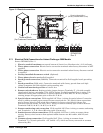
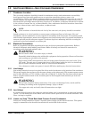
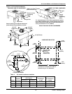
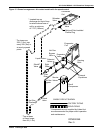
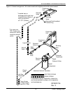
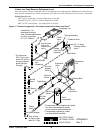
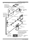
Variable Fan Speed Control Piping
A discharge line and a liquid line must be field-installed between the indoor unit and the outdoor
condenser. See Figures 15 and 16 for details.
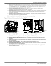
Variable Fan Speed Control Materials Supplied
•Built-in, pre-wired condenser control box
• Air-Cooled condenser
• Piping access cover to be reinstalled when piping is complete
• Bolts—four per leg (3/8" x 5/8")
• Terminal block for two-wire, 24V interlock connection between unit and condenser
• Condenser legs—four with 1-fan, 2-fan and 3-fan models; six with 4-fan models
Variable Fan Speed Control Leak Check and Evacuation Procedure
Proper leak check and evacuation can be accomplished only with all system solenoid valves open and
check valves accounted for.
1. If unit power is available, open the unit liquid line solenoid valves using the evacuation function
in the diagnostic section of the Liebert iCOM
®
control (refer to the Liebert iCOM user manual,
SL-18835). If unit power is not available, a field-supplied 24VAC / 75VA power source must be
directly connected to each of the unit solenoid valves.
2. For scroll and digital scroll compressors, connect refrigerant gauges to the suction rotalock valves
and discharge line Schrader valves (see Note above) on the compressor.
3. Open the service valves and place a 150 PSIG (1034 kPa) of dry nitrogen with a tracer of
refrigerant. Check system for leaks with a suitable leak detector.
4. After completion of leak testing, release the test pressure (per local code) and pull an initial deep
vacuum on the system with a suitable pump.
5. After four hours, check the pressure readings and, if they have not changed, break vacuum with
dry nitrogen. Pull a second and third vacuum to 250 microns or less. Recheck the pressure after
two hours. After completing this step, proceed to Variable Fan Speed Charging on page 29.
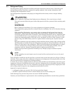
NOTE
Systems with a scroll or digital scroll compressor include a factory-installed check valve and
an additional downstream Schrader valve with core in the compressor discharge line. Proper
evacuation of the condenser side of the compressor can be accomplished only using the
downstream Schrader valve. See piping schematic (Figures 15 and 16).