3
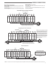
Single Stage Connections
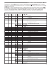
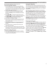
Refer to equipment manufacturers' instructions for specic system
wiring information.
This thermostat is designed to operate a single-transformer or two-
transformer system.
You can congure the thermostat for use with the following systems:
SINGLE STAGE gas, oil or electric.
HEAT PUMP TYPE 1 (HP 1). Single stage compressor system; gas
or electric backup.
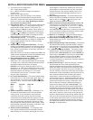
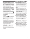
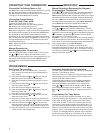
After wiring, see INSTALLER CONFIGURATION section for proper
thermostat conguration.
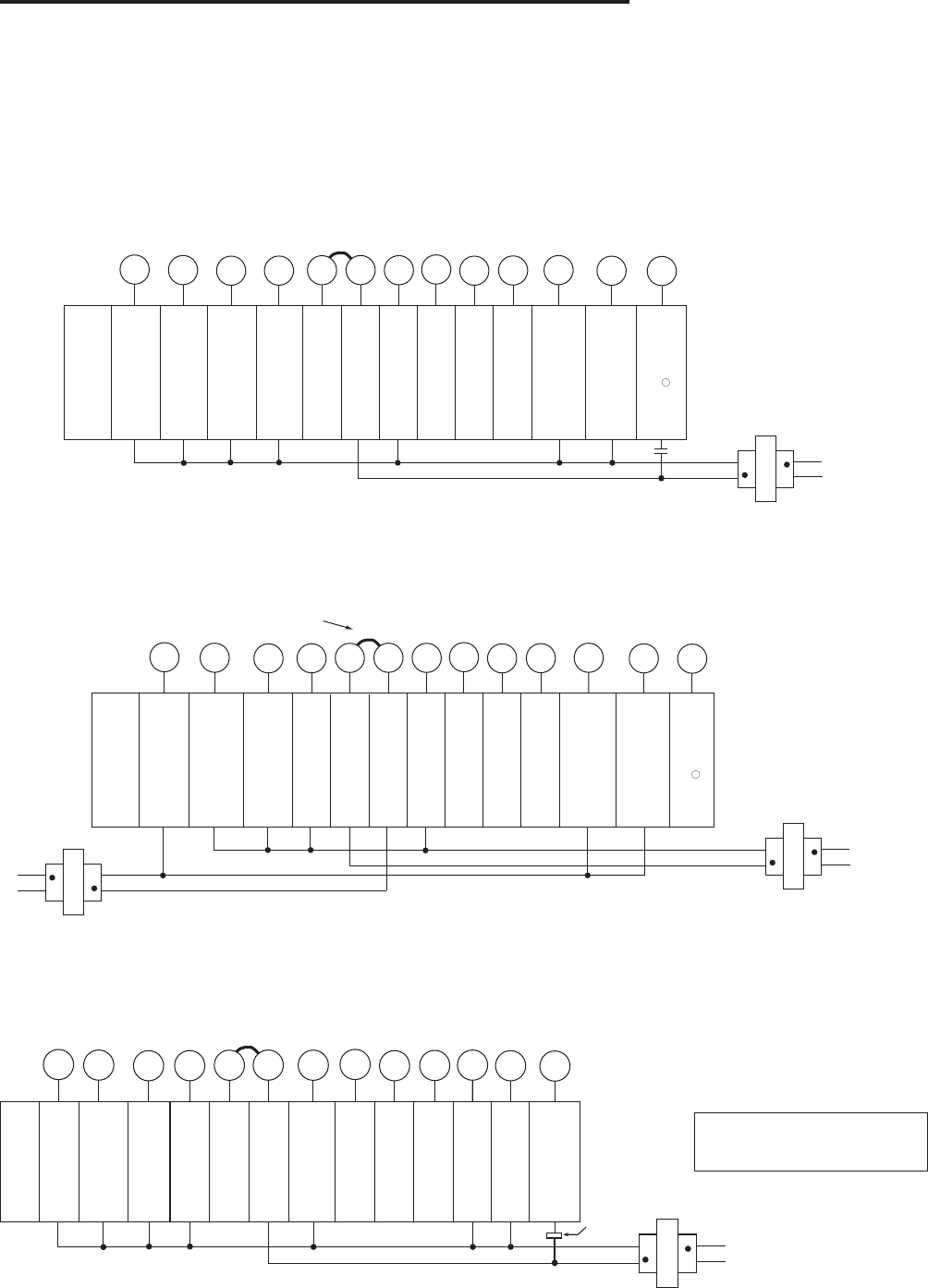
Single Stage System with Single Transformer
Single Stage with Two Transformers
Heat Pump Systems
Single
Stage
(SS)
Energiz-
ed in
Cool
Mode
Energized
in Heat
or Off
Mode
System
O
RH
+
B
CLASS II
TRANSFORMER
HOT
24VAC
NEUTRAL
120VAC
W
G
C*
-
Jumper
Energized
on call
for Cool
(Com-
pressor)
Blower/
Circula-
tor Fan
Energiz-
ed on
call for
Cool &
for Heat
(if ELE
is sel-
ected)
24 Volt
(Hot)
Cool
DC
supply
voltage
to re-
mote
Temp-
erature
Sensor
Remote
Temp-
erature
Sensor
signal
DC
Return
to
Remote
Temp-
erature
Sensor
Energized
on call for
Heat
Third
wire for
3-wire
zone
valve
Diagnostic
Indicator
(See
Note
)
Y
RC
S
6
L
{
To Remote Temperature Sensor
24 Volt
(Hot)
Heat
24 Volt
Com-
mon
(option-
al)
1
*Common connection required for fault or
malfunction indication and remote sensor.
*24 VAC common connection
optional for system operation.
**Dual fuel de-energizes
compressor when auxiliary heat is
energized.
Required for fault or malfunction indi-
cation, remote temperature sensor, or
for continuous backlight operation.
WIRING CONNECTIONS
Single
Stage
(SS)
Energized
in Cool
Mode
Energized
in Heat,
Off Mode
System
O
RH
+
B
CLASS II
TRANSFORMER
HOT
24VAC
NEUTRAL
120VAC
W
G
C*
-
Energized
on call
for Cool
(Com-
pressor)
Blower/
Circula-
tor Fan
Energiz-
ed on
call for
Heat or
Cool
(if ELE
is sel-
ected)
24 Volt
(Hot)
Cool
DC
supply
voltage
to re-
mote
Temp-
erature
Sensor
Remote
Temp-
erature
Sensor
signal
DC
Return
to
Remote
Temp-
erature
Sensor
Energized
on call for
Heat
Third wire
for 3-wire
zone valve
Y
RC
S
6
L
{
To Remote Temperature Sensor
24 Volt
(Hot)
Heat
24 Volt
Com-
mon
(option-
al)
CLASS II
TRANSFORMER
120VAC
HOT
24VAC
NEUTRAL
HEATING
COOLING
Diagnostic
Indicator
(See
Note
)
1
Jumper
Remove Jumper Wire
between RH & RC
NOTE: If continuous backlight or hardwired
power input are desired but do not function
in both HEAT and COOL modes, cut the
heating transformer 24V wires and tape off.
Connect the neutral circuit disconnected
from the heating transformer to the neutral
circuit of the cooling transformer. Discon-
nect the wire to the RH terminal and install
a jumper between RH and RC. Depending
on the system requirements, replace the
cooling transformer with a 75VA class II
transformer if needed.
*Common connection required for fault or
malfunction indication and remote sensor.
NOTE ➀: Connection for Call for Service diagnostic indicator compatible with mechanical or electronic condenser control with Comfort Alert
TM
.
Heat
Pump 1
(HP1)
Energized
in Cool
& Off
Mode
Energiz-
ed in
Heat/
Emer-
gency
Mode
System
O
RH
+
B
CLASS II
TRANSFORMER
HOT
24VAC
NEUTRAL
120VAC
W
G
C*
-
Jumper
1st
Stage
Heat
& Cool
(Com-
pressor)
**
Blower/
Circula-
tor Fan
Energiz-
ed on
call for
Heat or
Cool
24 VAC
(Hot)
Cool
DC
supply
voltage
to re-
mote
Temp-
erature
Sensor
Remote
Temp-
erature
Sensor
signal
DC
Return
to
Remote
Temp-
erature
Sensor
Auxil-
iary &
Emer-
gency
Heat
1st
Stage
Power
Closed
Conn-
ection
for
3-wire
zone
valve
Diagnostic
Indicator
(See
Note )
Y
RC
S
6
L
{
To Remote Temperature Sensor
24 VAC
(Hot)
Heat
24 VAC
Common
(optional)
Comfort
Alert II module
or similar
malfunction
module


