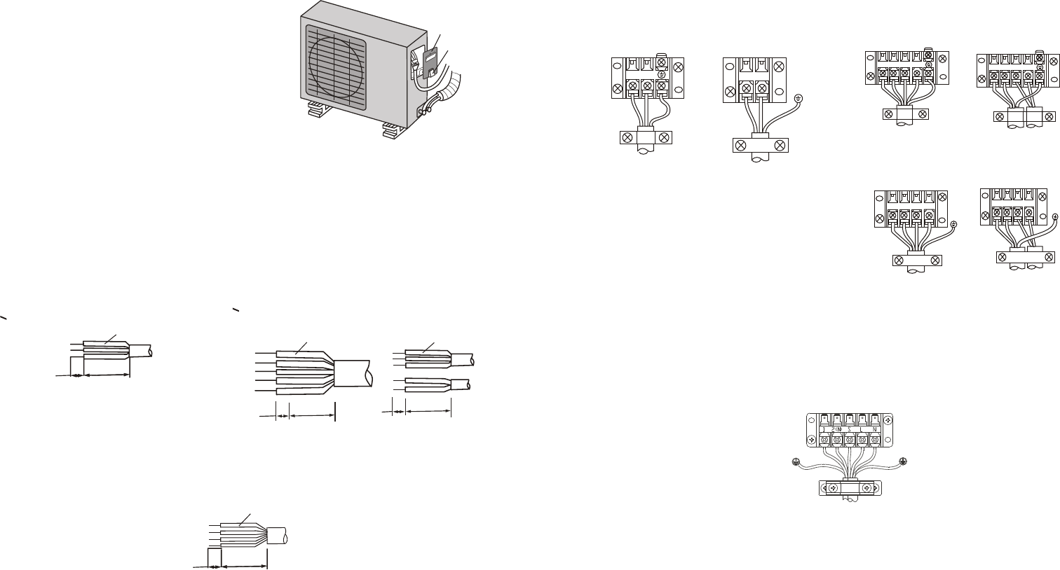
1. Remove the electrical control board
cover from the outdoor unit by
loosening the screw.
2. Connect the cables to the terminals as
identified with their respective
matched numbers on the terminal
block of indoor and outdoor units.
3. To prevent the ingress of water, from a
loop of the connective cable as
illustrated in the installation diagram of
indoor and outdoor units.
4. Insulate unused cords (conductors)
with PVC-tape.Process them so they
do not touch any electrical or metal
parts.
Connect the cable to the outdoor unit
Screw
Cover
40mm
40mm
10mm
10mm
< 18000 btu's (Cool model)CABLE
> 18000 btu's (Heat & Cool model)CABLE
Código del cable
< 18000 btu's (Heat & Cool model)CABLE
40mm
10mm
40mm
10mm
"Cable D”
"Cable F”
"Cable E”
or
Cable code
Cable code
Cable code
< 24
COOL MODEL
000 Btu's
MODELS
24000 Btu's
< 24000 Btu's
HEAT & COOL MODEL
or
or
or
or
or
or
"Connector A"
"Connector A"
"Connector A"
"Connector C”
"Connector B"
"Connector B"
"Connector D”
Cables
board
Cables
board
Cables
board
Cables
board
Cables
board
Cables
board
Cables
board
Wire connector of outdoor unit
Wire connector of outdoor unit
Wire connector of outdoor unit
Wire connector of outdoor unit
1
2(N)
1
2(N)
41
3
2(N)
41
3
2(N)
1
3
4
2(N)
41
3
2(N)
23 electrolux electrical work
electrical work electrolux 24


