


5
U.L. Model No.: CF205
How to Assembly Your Ceiling Fan (continued)
Your ceiling fan can be assembled with the light
kit and glass or without the light kit and glass. To
assemble without the light kit and glass, you will
use the no-light cover plate. In order to use the
no-light cover plate, the light sockets will need to
be removed from the light kit plate.
NOTE: In order to remove the light sockets, the
wires on the light kit plate will need to be cut.
MAKE SURE THIS IS THE NO LIGHT ASSEMBLY
DESIRED.
NOTE: If no light kit is to be used on the ceiling
fan, disregard Steps 4 and 5; proceed to “How to
Disassemble Your Light Kit for Cover Plate
Assembly Only”, then continue to Step 6.
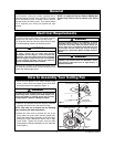
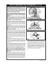
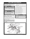
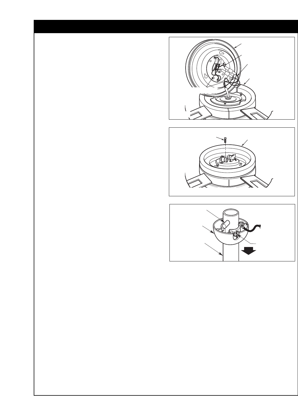
4. Connect the white wire from the light kit plate to the
white wire in the fan motor/ housing assembly
(Figure 3). Connect the black wire from the light kit
plate to the black wire in the fan motor/housing
assembly.
CAUTION: Before installing and tightening the
screws, be sure there are no wires pinched
between the light kit plate and the fan
motor/housing assembly.
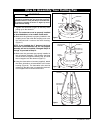
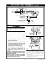
5. Remove one of the fan motor/housing assembly
screw (retain for later use). Position the light kit
plate on the fan motor/housing assembly aligning
the keyhole slots over the fan motor screws. Rotate
the light kit plate clockwise to engage the screws
into the keyhole slots. Reinstall the previous
removed screw. Tighten the three screws to secure
the light kit plate to the fan motor/housing
(Figure 4).
6. Carefully remove the fan assembly from the lower
foam pad. Turn the fan assembly over and posi-
tion it on the lower foam pad with the light kit plate
resting on the pad so that the top of the motor
faces up.
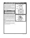
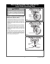
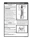
7. Remove the hanger ball by loosening the setscrew
in the hanger ball until the ball falls freely down the
downrod (Figure 5). Remove the pin from the
downrod, then remove the hanger ball. Retain the
pin and hanger ball for reinstallation in Step 15.
NOTE: If you have an eight-foot ceiling, you will
have to use the 6” downrod (supplied) in order to
maintain the necessary blade-to-floor clearance of
seven feet.
8. Unscrew the two upper setscrews (Figure 5) until
they clear the inside of the motor coupling. Then
separate, untwist and unkink the three 80” motor
leads. Route the motor lead wires through the
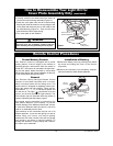
downrod. Align the clevis pin holes in the downrod
with the holes in the motor coupling. Install the cle-
vis pin and secure with the hairpin clip (Figure 9).
LIGHT KIT
PLATE
BLACK WIRE
BLUE WIRE
FAN MOTOR/
HOUSING
ASSEMBLY
WHITE WIRES
Figure 3
LIGHT KIT
PLATE
MOTOR
SCREW (3)
Figure 4
PIN
HANGER
BALL
SETSCREW
DOWNROD
Figure 5
The clevis pin must go through the holes in the
motor coupling and the holes in the downrod. Be
sure to push the straight leg of the hairpin clip
through the hole near the end of the clevis pin
until the curved portion of the hairpin clip snaps
around the clevis pin. The hairpin clip must be
properly installed to prevent the clevis pin from
working loose. Pull up on the downrod to make
sure the clevis pin is properly installed.