


Remote Control Procedures (continued)
13
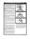
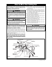
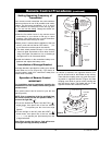
U.L. Model No.: CF205
COUPLING
COVER
MOTOR
HOUSING
REVERSE
SWITCH
Figure 24
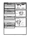
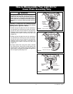
Setting Operating Frequency of
Transmitter
Your remote control transmitter has code switches
which must be set in one of 32 possible code combi-
nations. The five levers (numbered 1, 2, 3, 4, and 5)
on the switches are factory-set in the ON (up) posi-
tion. Do not use this setting
. Change the switch set-
tings as follows:
1.Slide the five switch levers in the remote control
(transmitter) to your choice of ON (up) or down
positions. Use a ball-point pen or small screwdriver
and slide the levers firmly up or down.
2.When power is restored after installation of the wall
control, push and hold the fan OFF button ( ) for
3 to 5 seconds to set the code in the receiver.
3. The sixth switch marked ON and I is for dimming
control of lights: Set switch to ON to allow for dim-
ming of the lights. Set switch to I for no dimming of
the lights such as for fluorescent bulbs.
4.Install the batteries in the transmitter battery com-
partment and replace the battery cover.
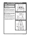
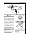
Installation of Storage Bracket
A storage bracket is provided for holding your remote
control when not in use (Figure 23). If you desire to
use the bracket, install it on a wall that is away from
excess heat or humidity.
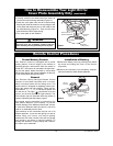
Operation of Remote Control
IMPORTANT
Fan installation must be completed, including the
installation of the fan blades, before testing of the
remote control.
Your remote control has full control of your fan and
light (Figure 23).
NOTE: Prior to operation of the fan and light from
the remote control, set the fan speed to HIGH (
....
)
and turn the light ON ( ).
1.To set the desired fan speed, hold the FAN ( )
button down, then press one of the four buttons
(
.
,
..
,
...
,
....
) to operate your fan from low to high
speeds.
2.To turn the light on and off, press the LIGHT ( )
button down, then press one of the four buttons
(
.
,
..
,
...
,
....
) to operate your light intensity from low
to high intensities.
Note: When turning the light on, light will turn on
at the light intensity previously selected.
HIGH TO LOW
BUTTONS
POWER
INDICATOR
LIGHT
LIGHT
BUTTON
FAN
BUTTON
STORAGE
BRACKET
TO INSTALL
BRACKET TO WALL:
SLIDE THE COVER UP
TO EXPOSE THE
SCREW HOLES FOR
INSTALLATION
COVER
SCREW
HOLES (2)
WALL
BRACKET
Figure 23
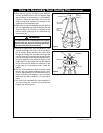
3. If airflow is desired in the opposite direction, turn
the fan off and wait for the blades to stop turning.
Then slide the coupling cover up, push the revers-
ing switch in opposite direction (Figure 24) Slide
coupling cover down to rest on motor housing and
turn the fan on again. The blades will turn in the
opposite direction and reverse the airflow.