


PLANNING YOUR INSTALLATION
PAGE 6
FACTORY BUILT FIREPLACES
This appliance is approved for installation into a listed
factory built solid fuel burning fireplace. The fireplace
firebox must accept the insert without modification other
than removing bolted or screwed together pieces such
as smoke shelf/deflectors, ash lips, screen or door
tracks and damper assemblies, that must be reinstalled
to restore the fireplace to its original operating condition
if the insert is removed and not replaced. The removal
of any part must not alter the integrity of the outer shell
of the pre-engineered fireplace cabinet in any way.
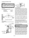
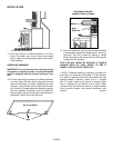
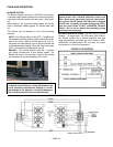
Venting Requirements for factory built fireplace:
The fireplace damper must be secured in the open po-
sition. When installed into a Factory Built Fireplace this
appliance requires the use of an 8” to 6” offset adapter.
The offset adapter aligns the appliance flue outlet with
fireplace flue and reduces flue outlet from 8” to 6” di-
ameter (8 to 6” Offset Adapter, Cat. No. 14M79). If flue
alignment is not necessary, a 8” to 6” bell reducer can
be used in place of the offset adapter. The required
vent is 6” diameter flex or rigid, UL1777 listed 2100° HT
liner or equivalent. The liner must extend from the
adapter at the flue outlet of the appliance to termination.
Do not face seal over fireplace chimney cooling air sys-
tems.
WARNING: Do not substitute the heat rated
2100°HT liner with any other type line or a fire
may result causing property damage, personal
injury or loss of life.
MASONRY FIREPLACES
This appliance is approved for installation into a ma-
sonry fireplace built to UBC Chapter 37 standards. Do
not remove brick or mortar form the masonry fireplace
to accommodate this appliance.
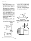
Venting Requirements for masonry fireplace:
The fireplace damper must be secured in the open po-
sition. As a minimum, a flue extension past the fireplace
header is required. A preferred installation is a positive
flue connection (sealing the throat of the chimney). This
appliance requires the use of a 6” or 8” diameter flex or
rigid single wall pipe, minimum 24/25 MSG black or
blued steel connector pipe (stainless steel recom-
mended). Offsets can be handled with an offset adapter
(it aligns starter pipe with fireplace flue). For more in-
formation on the offset adapters, see pages 8 and 24.
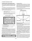
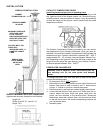
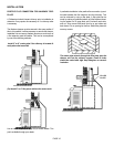
FIREPLACE CHIMNEY MAXIMUM SIZE TO ENSURE
PROPER DRAFT (Applicable to Masonry Fireplace
installations only).
The fireplace insert flue size is 8 inches in diameter,
which is approximately 50 square inches, the minimum.
The maximum flue size should be no more than (3)
three times the cross sectional area of the size of the
fireplace insert flue collar. In this case, that would be no
larger than a 14 inch diameter stack (area = approx.
154 sq. inches). To calculate area for a square or rec-
tangular flue, see below.
Note: Formulas for calculating Area:
Calculating area of a circle:
π x r
2
= Area (π = 3.1416, r = 1/2 diameter)
To calculate area of square or rectangle:
Width x Depth = Area
Notes:
It may be necessary to use a full-length liner to
achieve adequate draft for the appliance. A draft
gauge should .05” W.C., to .07” W.C. for opti-
mum performance.
This appliance is approved for all heatform style
fireplaces (masonry fireplace with a metal fire-
box liner).
.