


100402-07 Issue 0733 Page 8 of 18
defrost), the defrost relay is energized and defrost begins.
The factory setting is 60 minutes. However, if frost
accumulation is easily cleared, the optimum efficiency
setting is 90 minutes.
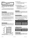
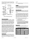
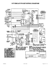
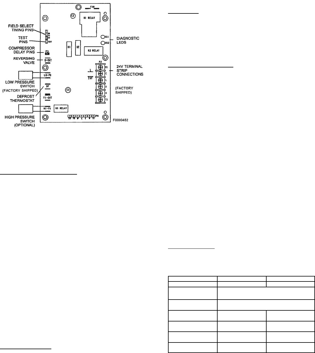
Outdoor Unit Defrost Control Board
Defrost Control Timing Pins
Each timing pin selection provides a different
accumulated compressor run time period for one defrost
cycle. This time period must occur before a defrost cycle
is initiated. The defrost interval can be adjusted to 30 (/T1),
60 (T2), or 90 (T3) minutes. The defrost timing jumper is
factory-installed to provided a 90-minute defrost interval.
If the timing selector jumper is not in place the control
defaults to a 90-minute defrost interval. The maximum
defrost period is 14 minutes and cannot be adjusted.
A TEST option is provided for troubleshooting. The
TEST mode may be started any time the unit is in the
heating mode and the defrost thermostat is closed or
jumpered. If the jumper is in the TEST position at power-
up, the control will ignore the test pins. When the jumper
is placed across the TEST pins for 2 seconds, the control
will enter the defrost mode. If the jumper is removed
before an additional 5 second period has elapsed ( 7
seconds total), the unit will remain in defrost mode until the
defrost thermostat opens or 14 minutes have passed. If
the jumper is not removed until after the additional 5
second period has elapsed, the defrost will terminate and
the test option will not function again until the jumper is
removed and re-applied.
Compressor Delay
The defrost board has a field-selectable function to
reduce occasional sounds that may occur while the unit is
cycling in and out of the defrost mode. The compressor will
be cycled "off" for 30 seconds going in and out of the
defrost mode when the compressor delay jumper is
removed.
NOTE: The 30 second "off" cycle is not functional when
jumpering the TEST pins.
Time Delay
The timed-off delay is 5 minutes long. The delay help to
protect the compressor from short-cycling in case the
power to the unit is interrupted or a pressure switch opens.
The delay is bypassed by placing the timer select jumper
across the TEST pins for 0.5 seconds.
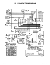
Pressure Switch Circuit
The defrost control incorporates 2 pressure switch
circuits. The optional high pressure switch connects to the
boards HI PS terminals. The low pressure switch is factory
installed.
During a single demand cycle, the defrost control will lock
out the unit after the fifth time that the circuit is interrupted
by any pressure switch wired to the control board. In
addition, the diagnostic LEDs will indicate a locked-out
pressure switch after the fifth occurrence of an open
pressure switch. The unit will remain locked out until power
to the board is interrupted, then re-established or until the
jumper is applied to the TEST pins for 0.5 seconds.
NOTE: The defrost control board ignores input from the
low-pressure switch terminals as follows:
! During the TEST mode,
! During the defrost cycle,
! During the 90 second start-up period,
! and for the first 90 seconds each time the reversing
valve switches heat/cool modes. If the TEST pins
are jumpered and the 5 minute delay is being by-
passed, the LO PS terminal signal is not ignored
during the 90 second start-up period.
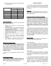
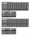
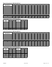
Diagnostic LEDS
The defrost board uses 2 LEDs for diagnostics. The
LEDs flash a specific sequence according to the condition.
Defrost Control board Diagnostic LED
Mode Green LED (DS2) Red LED (DS1)
No power to control OFF OFF
Normal operation/
power to control
Simultaneous Slow FLASH
Anti-short cycle
lockout
Alternating Slow FLASH
Low pressure switch
fault (Optional)
OFF Slow FLASH
Low pressure switch
lockout (Optional)
OFF ON
High pressure switch
fault (Optional)
Slow FLASH OFF
High pressure Switch
lockout (Optional)
ON OFF