


100402-07 Issue 0733 Page 7 of 18
10. Remove charge if superheat is low and add charge
if superheat is high.
Units with Indoor TXV
Units installed with TXV on indoor side, require charging
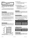
with the subcooling method.
1. Operate unit a minimum of 10 minutes before
checking charge.
2. Measure liquid service valve pressure by attaching
an accurate gage to service port. Determine
saturation temp. from T/P chart.
3. Measure liquid line temperature by attaching an
accurate thermistor type or electronic thermometer
to liquid line near outdoor coil.
4. Calculate subcooling (saturation temp.— measured
temp.).
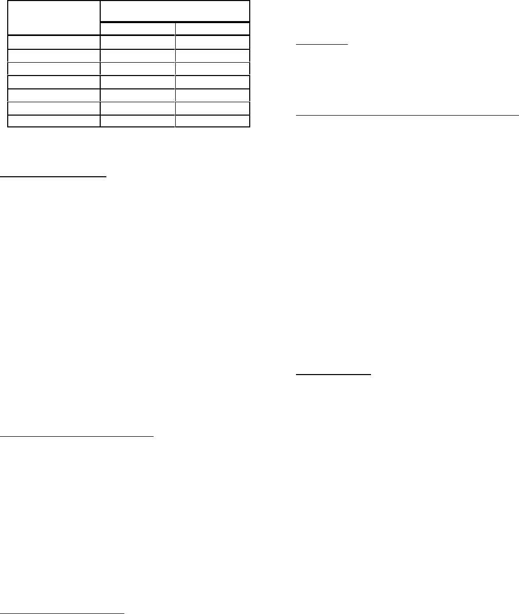
5. Find the point where required subcooling
temperature intersects measured liquid service valve
pressure.
6. Add refrigerant if subcooling is lower than table
below. Recover refrigerant if subcooling is high.
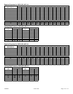
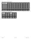
Heating Check Chart Procedure
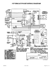
To check system operation during heating cycle, refer to
the Heating Check Chart located on back of control box
cover. This chart indicates whether a correct relationship
exists between system operating pressure and air
temperature entering indoor and outdoor units. If pressure
and temperature do not match on chart, system refrigerant
charge may not be correct. Do not use chart to adjust
refrigerant charge.
Charge must be rechecked again during the cooling
season.
Cold Weather Application
A cold weather accessory kit may be required for heat
pumps operating at ambient conditions below 25
/ F.
Supplemental heat should be provided for these conditions
due to the expected performance degeneration.
SYSTEM OPERATION
The outdoor unit and indoor blower cycle on demand
from the room thermostat. When the thermostat blower
switch is in the ON position, the indoor blower operates
continuously.
Filter Drier
The outdoor unit is equipped with a bi-flow filter drier. If
replacement is necessary, order new dryer according to the
service parts manual.
Emergency Heat Function (Room Thermostat)
An emergency heat function is designed into some room
thermostats. This feature is applicable when isolation of
outdoor unit is required or when auxiliary electric heat is
staged by outdoor thermostats. When the room thermostat
is placed in the emergency heat position, the outdoor unit
control circuit is isolated from power and field-provided
relays bypass the outdoor thermostats. An amber
indicating light simultaneously comes on to remind the
homeowner that he is operating in the emergency heat
mode.
Emergency heat is usually used during an outdoor unit
shutdown, but it should also be used following a power
outage. If power has been off for over an hour and the
outdoor temperature is below 50
/F (10/C). System should
be left in the emergency heat mode at least six hours to
allow the crankcase heater sufficient time to prevent
compressor slugging. This applies only to systems with
crank case heaters.
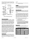
Defrost System
The defrost system includes two (2) components: a
defrost thermostat and a defrost control.
Defrost Thermostat
The defrost thermostat is located on the liquid line
between the check/expansion valve and the distributor.
When defrost thermostat senses 29
/F or cooler, the
thermostat contacts close and send a signal to the defrost
control board to start the defrost timing. It also terminates
defrost when the liquid line warms up to 60
/F.
Defrost Control
The defrost control board includes the combined
functions of a time/temperature defrost control, defrost
relay, diagnostic LEDs and terminal strip for field wiring
connections.
The control provides automatic switching from normal
heating operation to defrost mode and back. During
compressor cycle, the control accumulates compressor
run times at 30-, 60-, or 90-minute field-adjustable
intervals. If the defrost thermostat is closed when the
selected compressor run time interval ends (call for
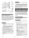
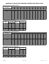
Model Required Subcooling
(± I
/F)
HP 13 HP 14
18 14 10
24 9 3
30 13 8
36 9 14
42 11 3
48 8 9
60 12 -