


100402-07 Issue 0733 Page 6 of 18
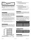
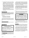
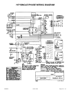
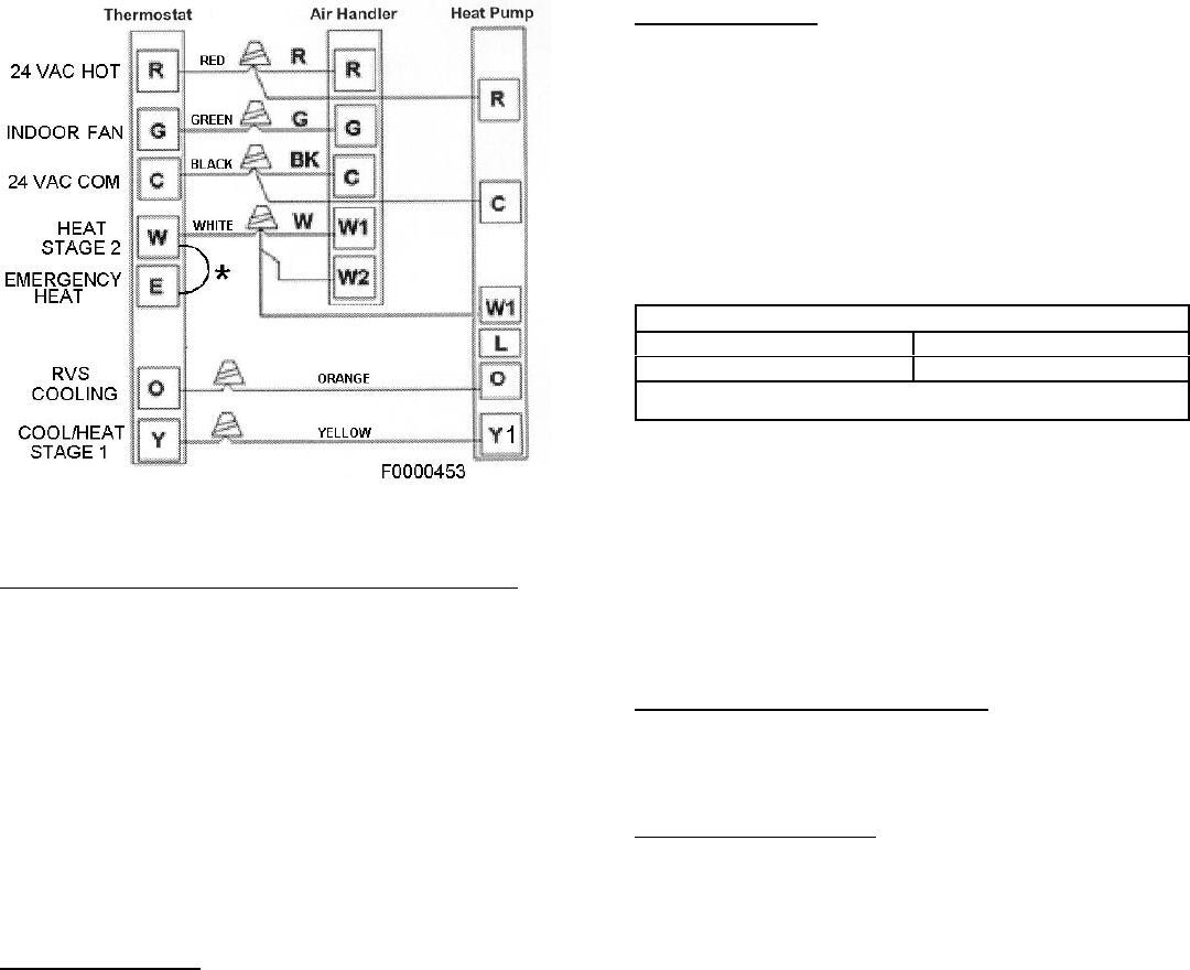
Heat Pump Application with Electric Heat
Emergency Heat (heating heat pump)
If selector switch on thermostat is set to the emergency
heat position, the heat pump will be locked out of the
heating circuit, and all heating will be electric heat ( if
applicable). A jumper should be placed between W and E
on the thermostat so that the electric heat control will
transfer to the first stage heat on the thermostat. This will
allow the indoor blower to cycle on and off with the electric
heat when the fan switch is in the AUTO position.
* Add Jumper on Subbase (Optional)
Start-Up Procedure
1. Check to ensure:
! Service valve and gage port caps are installed and
tightened.
! Voltage supply at unit agrees with nameplate
rating.
! Field wiring connections are tight and factory
wiring has not been disturbed and are tight.
! Indoor fan motor is on correct speed tap.
2. Set thermostat selector switch to OFF and fan control
switch to "Auto" is so equipped.
3. Close electrical disconnects to energize system.
4. Set room thermostat at desired temperature. Be sure
set point is below indoor ambient temperature.
5. Set the system switch of the thermostat on COOL (or
HEAT if applicable) and fan switch for continuous
operation (ON) or AUTO, as desired. There will be a
5 minute short cycle compressor delay on startup.
Operate unit for 15-20 minutes, then check the system
refrigerant charge.
6. Adjust refrigerant charge per "Adjusting Charge"
section.
Adjusting Charge
Factory charge is shown on the rating label located on
the access panel.
All split system heat pumps are factory charged for
15 feet of connecting line set and matched indoor fan
coil. Nameplate refrigerant charge should initially be
adjusted for line set lengths other than 15 feet. For line
sets shorter than 15 feet in length, remove charge. For line
sets longer than 15 feet, add charge. Oil charge is
sufficient for all line lengths.
Before final adjustment is made to the refrigerant charge,
it is imperative that proper indoor airflow be established.
Airflow will be higher across a dry coil versus a wet coil.
Blower charts are calculated with a dry or wet coil basis.
Recommended airflow is 350-450 CFM per ton (12,000
Btuh) through a wet coil. Refer to indoor unit instructions
for methods of determining air flow and blower
performance.
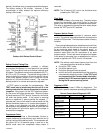
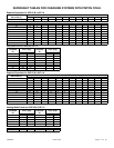
Cooling Cycle Charge Adjustment
The optimum method for checking the charge is by
weight. However the following methods may be used
to confirm the proper charge:
Units with Indoor Pistons
Units installed with indoor pistons require charging with
the superheat method.
The following procedure is valid when indoor airflow is
within ± 20% of its rated CFM.
1. Operate unit a minimum of 10 minutes before
checking charge.
2. Measure suction pressure by attaching a gage to
suction valve service port. Do not use compressor
suction port. Determine saturation temp from T/P
chart.
3. Measure suction temperature by attaching an
accurate thermistor type or electronic thermometer
to suction line at service valve.
4. Calculate superheat (measured temp. — saturation
temp.).
5. Measure outdoor air dry-bulb temperature with
thermometer.
6. Measure indoor air (entering indoor coil) wet-bulb
temperature with a sling psychrometer.
7. Compare superheat reading at service valve with the
chart located on control box cover.
8. If unit has a higher suction line temperature than
charted temperature, add refrigerant until charted
temperature is reached.
9. If unit has a lower suction line temperature than
charted temperature, reclaim refrigerant until charted
temperature is reached.
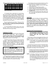
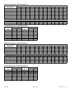
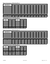
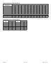
Refrigeration Charge Adjustment
Liquid Line Diameter Oz. Per Linear Foot *
3/8" .6
* Factory charge for series is for 15' (ft.) line sets and matched fan
coil.