


19
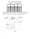
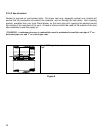
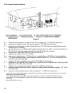
3.3.4.6 Vent terminal locations
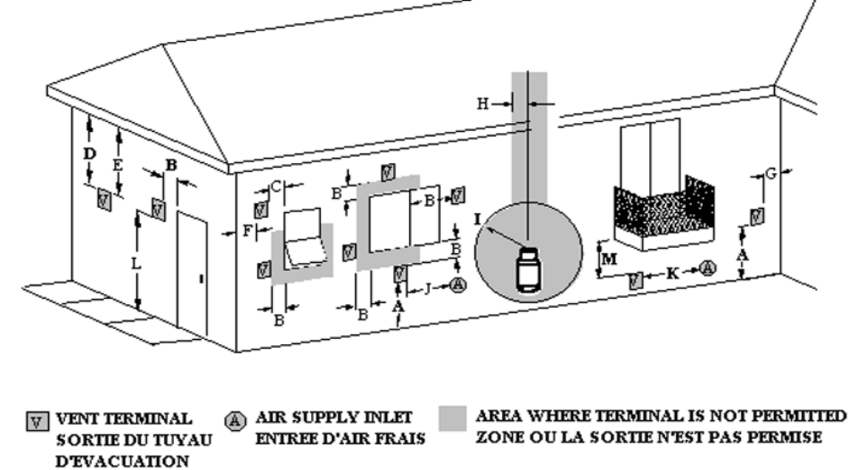
Figure 7
A = clearances above grade, veranda, porch, deck, or balcony [* 12" (305 mm) minimum]
B = clearance to window or door that may be opened [* 12" (305 mm) minimum]
C = clearance to permanently closed window [minimum 12" (305 mm) recommended to prevent
condensation on window]
D = vertical clearance to ventilated soffit located above the terminal within a horizontal distance of
24" (610 mm) from the centre-line of the terminal 23" (584 mm) minimum
E = clearance to unventilated soffit 23" (584 mm) minimum
F = clearance to outside corner = 0" (0 mm)
G = clearance to inside corner = 0" (0mm) to non-combustibles, or 8" (203mm) to combustibles
H = * not to be installed above a meter/regulator assembly within 36" (914 mm) horizontally from
the centre-line of the regulator
I = clearance to service regulator vent outlet [* 72" (1829 mm) minimum]
J = clearance to non-mechanical air supply inlet to building or the combustion air inlet to any other
appliance [* 12" (305 mm) minimum]
K = clearance to a mechanical air supply inlet [* 72" (1829 mm) minimum]
L = clearance above paved side-walk or a paved driveway located on public property [* 84" (2134
mm) minimum]
M = clearance under veranda, porch, deck, or balcony [* 12" (305 mm) minimum ]
a vent shall not terminate directly above a side-walk or paved driveway which is located between two single family
dwellings and serves both dwellings*
only permitted if veranda, porch, deck, or balcony is fully open on a minimum of 2 sides beneath the floor*
* as specified in CGA B149 Installation Code (1991) NOTE: local codes or regulations may specify different
clearances
* follow ANSI Z223.1 for U.S.A.