


26
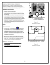
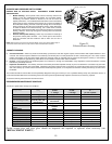
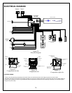
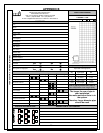
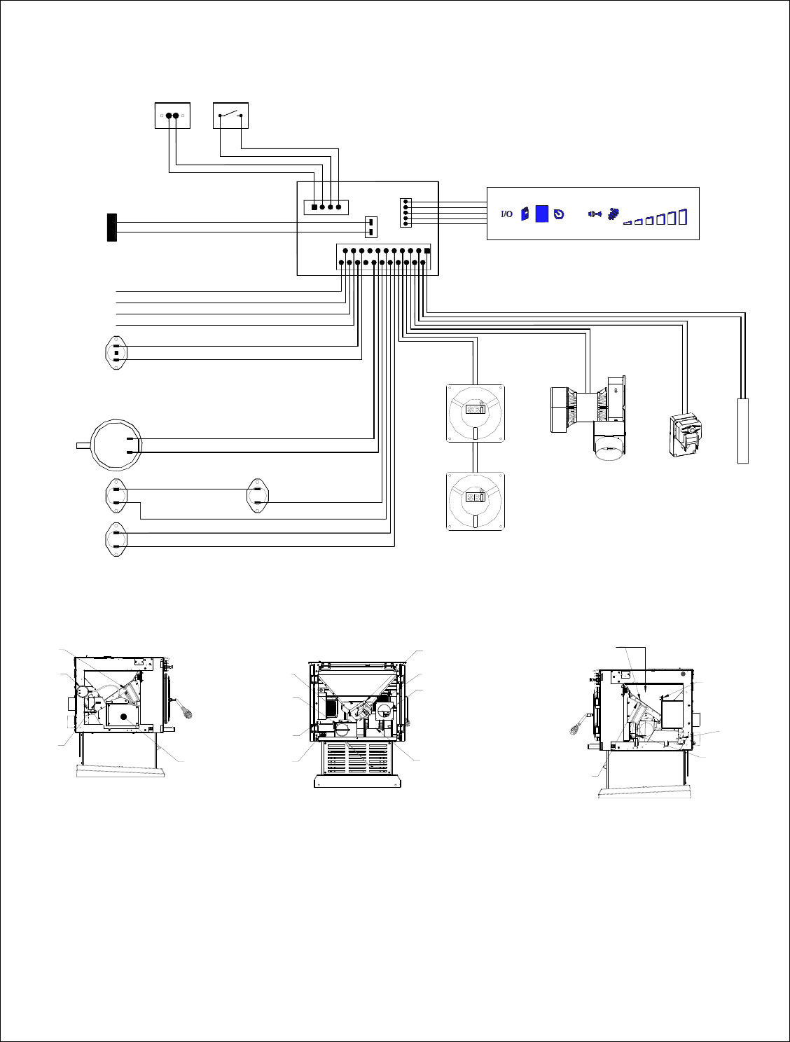
ELECTRICAL DIAGRAM
F-160
N.O.
CONTROL
BOARD
L-250
N.C.
L-250
RESET
N.C.
FRAME GROUND
L1(LINE NO CONNECTED)
L2(LINE COMMON)
L1(LINE HOT)
THERMOSTAT
TERMINALS
N.O.
HOPPER LID
SWITCH
N.O.
CONVECTION
BLOWER
COMBUSTION/EXHAUST
BLOWER
AUGER
MOTOR
IGNITER
AIR FLOW
PRESSURE
SWITCH
N.O.
L-250
N.C.
THERMISTOR
DISPLAY BOARD
Figure 26
Electrical diagram
PRESSURE
SWITCH
CLEANING
ACCESS
PANEL
THERMISTOR
CONVECTION
BLOWER
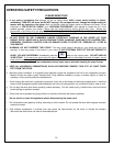
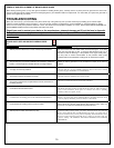
Figure 27
Components left side
EXHAUST/COMBUSTION
BLOWER
THERMOSTAT
TERMINAL
AUGER
MOTOR
FRESH AIR
INTAKE
EXHAUST
CONVECTION
BLOWER
CONVECTION
BLOWER
POWER
CORD
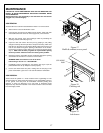
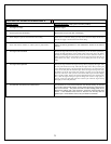
Figure 28
Components rear
HIGH TEMPERATURE
SWITCH F-160
HIGH TEMPERATURE
SWITCH L-250
AUTOMATIC
IGNITER
AIR SUPPLY
CONTROL
HIGH TEMPERATURE
SWITCH L-250
MANUAL RESET
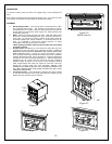
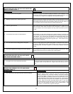
Figure 29
Components right side
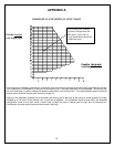
ELECTRIC SHOCK
In order to verify the grounding and polarity of the power outlet, the control board sends a low voltage impulse to the stove’s frame.
If the polarity is wrong or if the outlet is not properly grounded, you may feel an electric shock when you touch the stove; this low voltage impulse is
harmless and connecting your stove to a grounded outlet with the right polarity will keep this from happening and protect your electronics against
damages from power surge.