


7
INSTALLATION INSTRUCTIONS
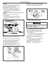
3. A 3/8” diameter hole will be needed to route the cable
through the wall.
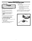
B. CONTROL CABLE INSTALLATION
A 4-conductor control cable must be routed from the roof opening to
the Comfort Control Center™.
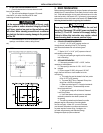
1. Choose the shortest, most direct route from the 14-
1/4” (±1/8”) opening to the Comfort Control Cen-
ter™ location selected. Leave 6” of cable extending
through the wall.
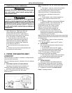
2. Thecontrolcablethatshouldbeusedisaat,4-
conductor telephone cable.
3. The control cable must be terminated with two (2) RJ-
11-4C-6P telephone connectors. Refer to the crimp tool
manufacturer for crimping instructions.
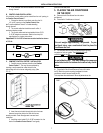
Important: RJ-11-4C-6P connectors must be installed as shown
in FIG. 4A.
C. COMFORT CONTROL CENTER™ INSTALLATION
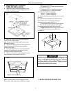
1. Carefully remove the base plate from the Comfort
Control Center™. This may be accomplished by
inserting a small screwdriver under the tab on the
bottom edge of the front cover and gently prying. (See
FIG. 5).
2. Insert the control cable through the hole in the base
plate and mount the plate to the wall with the two
screws provided. Check the alignment to ensure level
installation.
3. Install the control cable RJ-11-4C-6P connector into the
back of the Comfort Control Center™ and gently
press onto the base plate.
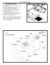
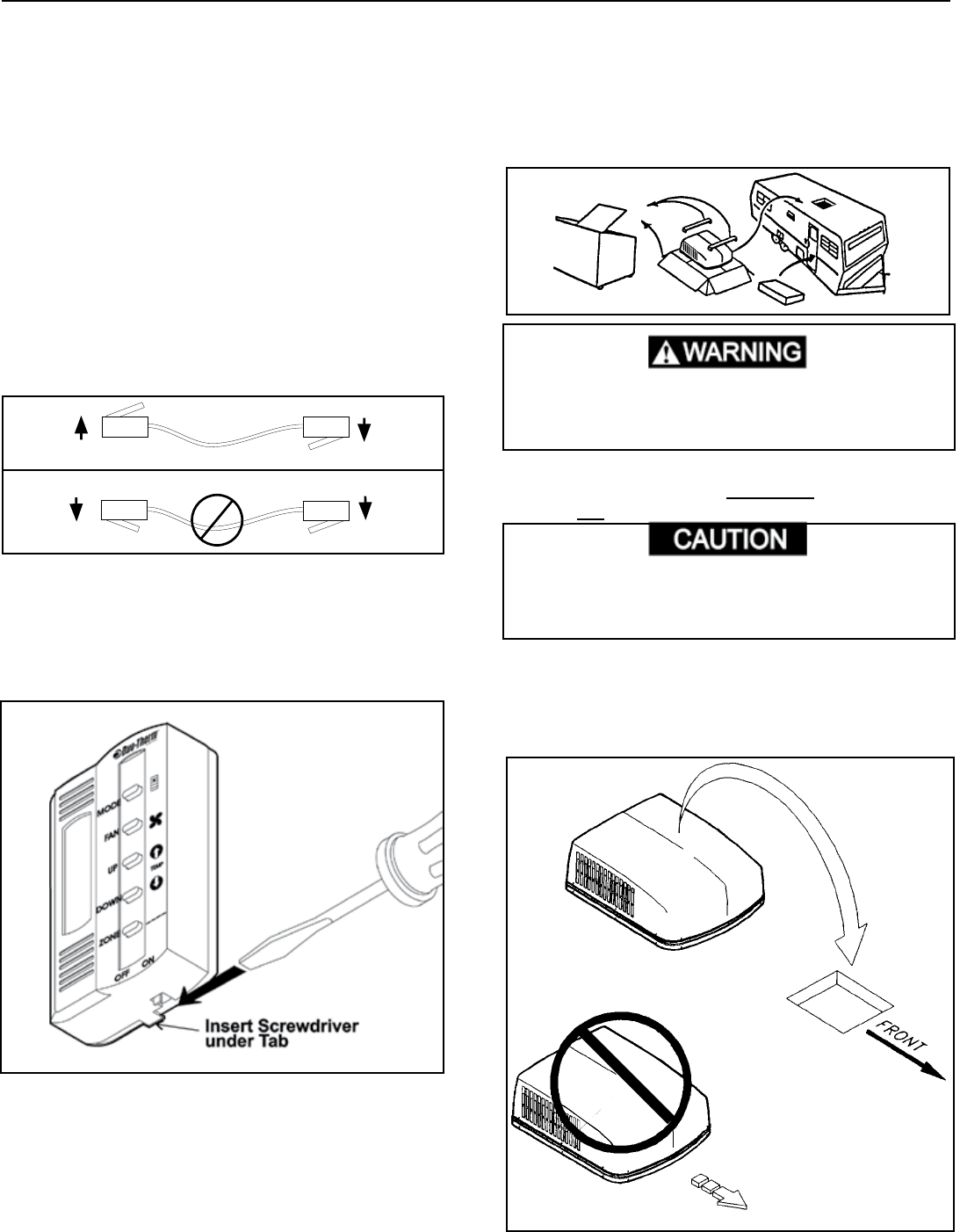
5. PLACING THE AIR CONDITIONER
ON THE ROOF
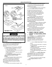
A. Remove the Air Conditioner from the carton
and discard.
B. Place the Air Conditioner on the roof.
This unit weighs approximately 100 pounds. To pre-
vent back injury, use a mechanical hoist to place Air
Conditioner on roof.
C. Lift and place the unit over the prepared opening using
the gasket on unit as a guide. The exposed coil goes
toward the rear of the RV.
Do not slide the unit. This may damage the neoprene
gasket attached to the bottom and create a leaky instal-
lation.
D. Place the Air Box Kit and Electronic Control Kit inside
the RV. Both kits contain mounting hardware for the air
conditioner and will be used inside the RV.
This completes the outside work. Minor adjustments can be
FIG. 5
FIG. 7
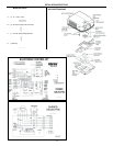
FIG. 6