


10
INSTALLATION INSTRUCTIONS
8. SYSTEM CONFIGURATION, RESET
& CHECKOUT
Nowthatthesystemisinstalled,itisnecessarytoconguretheelec-
tronics and check all operations.
Refer to the Operating manual for a description of the air conditioner
operation.
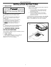
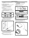
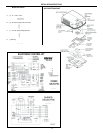
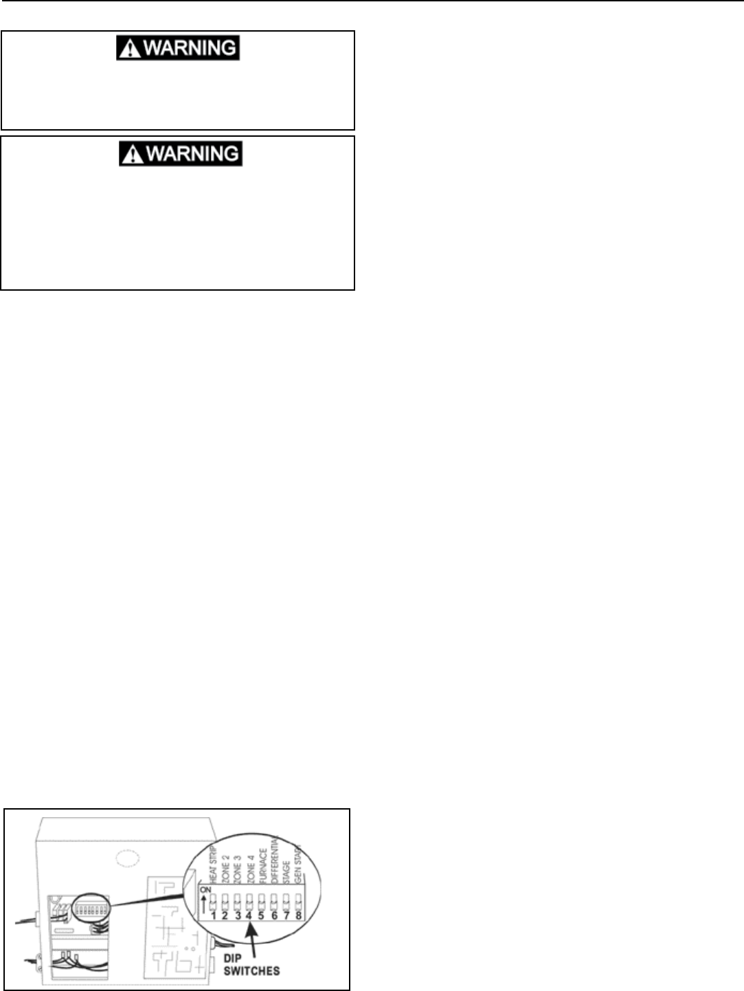
A. ELECTRONIC CONTROL KIT CONFIGURATION
Depending on the equipment options installed by the
recreational vehicle manufacturer, the appropriate dip
switches will need to be switched to the “ON” position.
See FIG. 14. Placing the switch in the “ON” position
selects that option.
B. CONNECTION OF 120 VOLT POWER SUPPLY
Disconnect 120 volt AC. Failure to follow these instruc-
tions could create a shock hazard causing death or
severe personal injury.
This product is equipped with a 3-wire (grounded)
system for protection against shock hazard. Make sure
that the appliance is wired into a properly grounded 120
volt AC circuit and the polarity is correct. Failure to do
so could result in death, personal injury or damage to
the equipment.
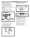
1. Route the 120 VAC supply line through the strain
relief in Electronic box. Tighten strain relief, mak-
ing sure enough wire is inside electronic box to
connect with unit 120 VAC wire. Tighten screws on
strain relief connector being careful not to pinch and
cut into the insulation on power supply leads.
2. Connect the white to white; black to black; and
green to green or bare copper wire using appropri-
mately sized twist wire connectors. Tape the twist
wire connectors to the supply wiring to assure they
do not vibrate off. See FIG. 14.
3. Push the wires into the box and tighten the strain
relief.
4. Install the cover (part of the mounting hardware) with
the one blunt point screw provided.
Note: Dip switches are in the “OFF” position when shipped from the
factory.
1. Zone selection - when two or more units are installed
and controlled by one Comfort Control Center, the
second unit becomes Zone 2, the third unit Zone 3
and the fourth unit Zone 4. The appropriate zone dip
switch must be set in each electronic control kit for
Zone 2, 3 and 4.
2. Furnace selection - when a furnace has been con-
nected to a zone, place the furnace dip switch “ON”
for that zone.
3. Differential - differential is the temperature difference
between the “ON/OFF” cycle of the thermostat. The
normal differential is preset in the circuit board with
the dip switch set to the “OFF” position. In some
situations, it may be necessary to decrease the
Differential. The location of the thermostat may
create a condition where the normal Differential will
not maintain your comfort zone. If this occurs, the
Differential can be shortened by placing the Differen-
tial dip switch to the “ON” position.
Note: Setting the Differential dip switch should only be required when
installation conditions are less than desirable and is not covered under
the limited warranty.
4. Stage selection - stage is not used on these units.
Leave in the “OFF” position.
5. Gen start selection - leave in the “OFF” position.
B. SYSTEM RESET
After setting the dip switches in the electronic control
kit, do a system reset.
1. Turn the ON/OFF switch to the “OFF” position.
2. Simultaneously depress and hold the MODE and
ZONE push-buttons while turning the ON/OFF switch
to “ON”. FF should appear in LCD display until the
mode and zone push-buttons are released.
3. Whenadipswitchisturnedonafterinitialcongura-
tion, a system reset will need to be done before the
Comfort Control Center will recognize the updated
selection.
C. SYSTEM CHECKOUT
Verify that all features of the installed system work.
Check fan speeds, cooling mode, furnace (if connected)
and heat strip. If the features do not work, check all wiring
andconrmthatthecorrectoptionshavebeenselected
on the Electronic Control Box. See Comfort Control
Center™ Operating Instructions.
FIG. 14