


5
INSTALLATION INSTRUCTIONS
C. AFTER LOCATION HAS BEEN SELECTED:
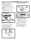
1. Check for obstructions in the area where air condi-
tioner will be installed.
2. The roof must be designed to support 130 pounds
when the RV is in motion. Normally a 200 lb. static
load design will meet this requirement.
It is the responsibility of the installer of this air condi-
tioner system to ensure structural integrity of the RV
roof. Never create a low spot on the roof where water
will collect. Water standing around the air conditioner
may leak into the interior causing damage to the product
and the RV.
3. Check inside the RV for air box obstructions (i.e. door
openings,roomdividers,curtains,ceilingxtures,
etc.)
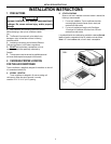
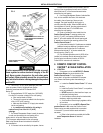
3. ROOF PREPARATION
Before preparing the ceiling opening, the type of system options must be
decided upon. If a remote sensor is to be used, provision must be made
for it. If the load shed option is to be used, wires must be run from the
load shed control to the Dometic A/C. If a furnace is to be connected,
wires must be run from the furnace to the Dometic A/C. Read all of the
following instructions before beginning the installation.
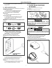
There may be electrical wiring between the roof and
the ceiling. Disconnect 120 volt AC power cord and the
positive (+) 12 volt DC terminal at the supply battery.
Failure to follow this instruction may create a shock
hazard causing death or severe personal injury.
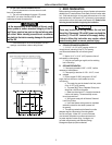
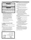
A. CEILING OPENING REQUIREMENTS
1. A 14-1/4” x 14-1/4” (±1/8”) opening must be cut
through the roof and ceiling of the RV. This opening
must be located between the roof reinforcing mem-
bers.
2. Mark a 14-1/4” x 14-1/4” (±1/8”) square on the roof
and carefully cut the opening.
3. Using the roof opening as a guide, cut the matching
hole in the ceiling.
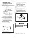
B. OPENING PREPARATION
1. If the opening exceeds 14-3/8” x 14-3/8”, it will be
necessary to install spacers.
2. If the opening is less than 14-1/8” x 14-1/8”, it must
be enlarged.
3. Route a copper 12 AWG, with ground, 120 VAC
supply line from the fuse or circuit breaker box to the
roof opening.
a. This supply line must be located in the front portion
of the 14-1/4” (±1/8”) opening.
b. The power MUST be on a separate 20 amp time
delay fuse or HACR circuit breaker.
c. Make sure that at least 15” of supply wire extends
into the roof opening. This ensures easy connec-
tion at the junction box.
d. Wiring must comply with all National, State and
Local Wiring Codes.
e. Use a steel sleeve and a grommet or equivalent
methods to protect the wire where it passes into
the opening.
4. The opening created must be framed to provide
adequate support and prevent air from being drawn
from the roof cavity. Lumber 3/4” or more in thickness
must be used. Remember to provide an entrance hole
for power supplies, furnace wiring, 4-conductor con-
trol cable, remote sensing and load shed (Energy
Management System) options as desired.
FIG. 2