


6
INSTALLATION INSTRUCTIONS
It is the responsibility of the installer of this air condi-
tioner system to ensure structural integrity of the RV
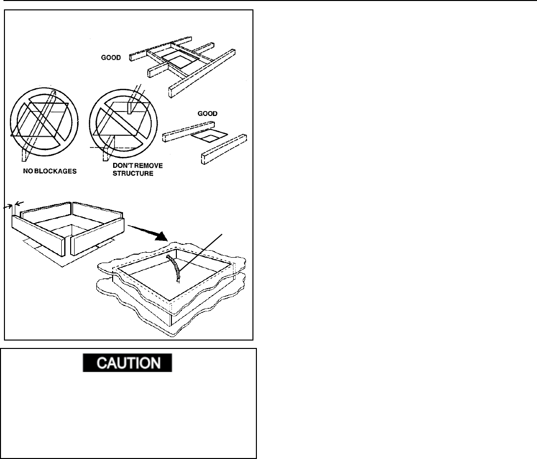
roof. Never create a low spot on the roof where water
will collect. Water standing around the air conditioner
may leak into the interior causing damage to the product
and the RV.
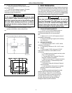
5. The 14-1/4” x 14-1/4” (±1/8”) opening is part of the
return air system of the Air Conditioner and must be
nishedinaccordancewithNFPAStandard501C
Section 2.7.
6. Route a dedicated 12 VDC supply line (18-22 AWG)
from the RV’s converter or battery to the roof opening.
a. Wire must be fused at 3 Amps.
b. This supply line must be located in the front portion
of the 14-1/4” (±1/8”) opening.
c. Make sure that at least 15” of supply wire extends
into the roof opening.
d. In a multiple zone installation, this wiring is
required in only one of the 14-1/4” (±1/8”)
openings.
7. If a Remote Temperature Sensor is used, the connec-
tor end must be routed to the roof opening of the
system which it will control. Make sure that at least
15” of the sensor cable extends into the roof opening.
Refer to the Remote Sensor Instructions for details of
the installation.
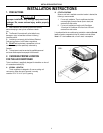
8. If a furnace is to be controlled by the system, the two
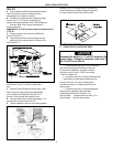
15”
min.
3/4” MIN.
FRAME OPENING SO IT WON’T COL
-
LAPSE WHEN BOLTING DOWN AIR
CONDITIONER
LEAVE ACCESS FOR POWER
SUPPLY WIRING
furnace thermostat leads must be routed to the roof
opening of the air conditioner that will control it. Make
sure that at least 15” of the furnace thermostat wires
extend into the roof opening.
9. If an Energy Management System (load shed fea-
ture) is to be used with the control, two wires must
be routed to the roof opening of the zone to be
managed. The signal required for this function is
normally open relay contact. When the EMS calls for
the compressor to shut off, the relay contacts should
close. Make sure at least 15” of the EMS wires
extend into the roof opening.
10. Route a 4-conductor control cable from the
Comfort Control Center™ mounting position into
the 14-1/4” (±1/8”) roof opening. Make sure that at
least 15” of the wire extends into the roof opening and
6” extend from the wall at the mounting position of the
Comfort Control Center™.
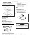
11. In the event that other Air Conditioners are installed
(additional zones) an additional 4-conductor control
cable must be routed to the other Air Conditioners.
Make sure that at least 15” of the wire extends into
the roof opening. (See Fig. 16)
12. If an automatic generator start kit (AGS) will be
installed, a 4-conductor control cable must be routed
from the last air conditioner to location of AGS kit.
Follow AGS kit instructions for installation.
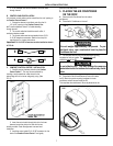
4. DOMETIC COMFORT CONTROL
CENTER™ & CABLE INSTALLATION
A. LOCATION
1. If the system is to be used WITHOUT a Remote
Temperature Sensor, the proper location of the
Comfort Control Center™ is very important to
ensure that it will provide a comfortable RV tempera-
ture. Observe the following rules when selecting a
location:
a. Locate the Comfort Control Center™ 54” above
theoor.
b. Install the Comfort Control Center™ on a partition,
not on an outside wall.
c. NEVER expose it to direct heat from lamps, sun
or other heat producing items.
d. Avoid locations close to doors that lead outside,
windows or adjoining outside walls.
e. Avoid locations close to supply registers and the
air from them.
2. If the system is to be used WITH a Remote Tem-
perature Sensor in ALL zones, the Comfort Control
Center may be mounted anywhere that is convenient
in the coach. Try to avoid hard to reach and hard to
see areas.
a. Refer to the instructions provided with the Re-
move Temperature Sensor for details of
installation.
FIG. 3