7
INSTALLATION INSTRUCTIONS
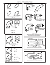
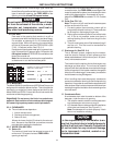
4. Sudden contractions in air stream
5. Sudden expansions in air stream
2.1.7 REGISTERS, DIFFUSERS, AND GRILLE SELEC-
TION
One of the most important considerations in designing a
conditioning system is the selection of the registers, diffus-
ers and grills. Even though a system delivers the required
amount of conditioned air to the room, discomfort results if
the air is not satisfactorily distributed. Achieving good air
distribution is as much an art as it is a science. Careful
consideration must be given to the design of the air distribu-
tion system. A forced air system is only as efficient as its
air delivery components.
Whenever a jet of conditioned air is admitted into a room it
affects all the air within that room. Movement of the supply air
induces adjacent room air to move along with it. This process
of the supply air dragging along the room air and setting it in
motion is called “entrainment” of the room air. As the room
air mixes with the supply air, the temperature difference
between them is reduced. This effect is even more pro-
nounced with a spreading jet than with a non—spreading jet
because of the greater surface area.
2.1.8 ROOM AIR DISTRIBUTION
The final evaluation of air distribution in a space is determined
by the occupants’ comfort level. In general, a person is
thermally comfortable when their body heat loss just equals
their heat production.
During cooling, currents carry warm air up the wall to ceiling
level, and stratification forms from the ceiling down. The
solution is to project cool air into this region near the ceiling.
Performance of any supply outlet is related to initial velocity
and area. As it leaves the outlet, an air jet becomes a mixture
of supply and room air, expanding due to the induction of
room air.
The buoyant forces with non-isothermal jets cause the jet to
rise during heating and drop during cooling. If the jet is
projected parallel to and within a few inches of a surface, the
jet performance will be affected by the surface, which limits
the induction on the surface side of the jet. This creates a low
pressure region between the jet and the surface, which draws
the jet toward the surface. In fact, this effect will prevail if the
angle of discharge between the jet and surface is less than
40°. The surface effect will draw the jet from a ceiling outlet
to the ceiling. Surface effect increases the throw for all types
of outlets and decreases the drop for horizontally projected
air streams.
The air stream from the outlet tends to “hug” the surface. As
a matter of fact, this characteristic is almost essential for
good comfort air conditioning. Therefore, rather than trying to
direct the air away from surfaces, the surfaces should be
used intentionally. Note that where the surfaces are used
most effectively, the high velocity portions of the air stream
have less tendency to enter the occupied zone of the space.
2.2 HOW ROOM AIR MOTION IS RELATED TO
OUTLET PERFORMANCE
The room air near the supply air stream is entrained by the
air stream and, in turn, is replaced by other room air. The
room air always moves toward the supply air. The only
general statement that can be made regarding room air
motion and the number of air changes is that 8 to 10 air
changes per hour are required to prevent formation of stag-
nant regions.
For most applications, a better approach is to supply air in
such a way that the high velocity air stream from the outlet
does not enter the occupied zone. It is practical to consider
the region within 12 inches of the walls as outside the
occupied zone as well as the region above the heads of the
occupants.
Supply air should be spread in a thin layer over the surfaces,
to surround the occupied zone with conditioned air. Air within
the occupied zone will then move toward the total air stream,
the mixture of primary and room air. The room air carries the
load with it into the air stream and room conditions are
maintained by constant mixing of room and supply air.
Improper installation may damage equipment,
could endanger life, cause serious injury and/
or property damage.
WARNING
!
It is the responsibility of the R.V. manufac-
turer to assure that structural integrity is main-
tained throughout the coach.
CAUTION
2.3 SPECIFICATIONS & REQUIREMENTS
Since it is necessary to install all or part of the duct work in
the ceiling, sidewall or floor.
The manufacturer should review each floor plan to determine
proper duct design and register location.
The Dometic Product Engineering and Application depart-
ments are available for recommendations and suggestions.
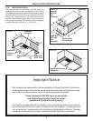
If the conditioned air is to be discharged from the
ceiling area, the minimum roof cavity thickness for
proper installation measured between the roof and
ceiling structure is 4 inches. This does not include
space required for insulation of the ductwork.
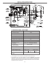
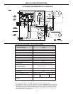
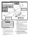
The air conditioner was designed to allow flexibility for layout
of duct work and the types of registers employed. To ensure
air conditioner maximum performance, certain parameters
must be adhered to. Refer to Figures 3.4 for duct sizing and
grill placement


