15
INSTALLATION INSTRUCTIONS
B. Route a dedicated DC supply line (18-22 AWG copper
conductors) from the Converter or Battery to the
unit's electrical box. Connect with wire nuts positive
(+) DC to the red wire; Negative (-) DC to the black
wire.
C. Route thermostat wires from the furnace (if applicable)
to the electrical box and attached them to the blue
wires extending from the main board. The polarity of
these connections does not matter.
D. Route the Energy Management System 2 wires (if
applicable) to the electrical box and connect them to
the yellow wires extending from the main board. The
polarity of these wires does not matter.
Note: If yellow wires are not used and a circuit is made
between them, the unit will fail to operate.
3.4.2 CONTROL CABLE INSTALLATION
A. A 4-conductor flat control cable, must be routed be-
tween the Comfort Control Center (CCC) and the elec-
trical box. The maximum length of all control
cables is seventy-five (75) feet.
B. Select the shortest direct route between Comfort
Control Center
TM
and the electrical box for the sys-
tem.
C. A 3/8" diameter hole will be needed to route the con-
trol cable through the wall.
D. Leave 6" of cable extending through the wall.
E. The cable that must be used is a 4-conductor flat
control cable.
F. The cable must be terminated with two RJ-11 tele-
phone connectors. Refer to the crimp tool manufac-
turer for crimping instructions. Be sure the cable
is installed correctly into the connector before it is
crimped. Polarity is important and a standard
pre-made telephone cable will not work.
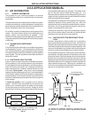
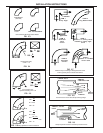
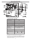
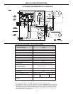
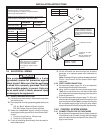
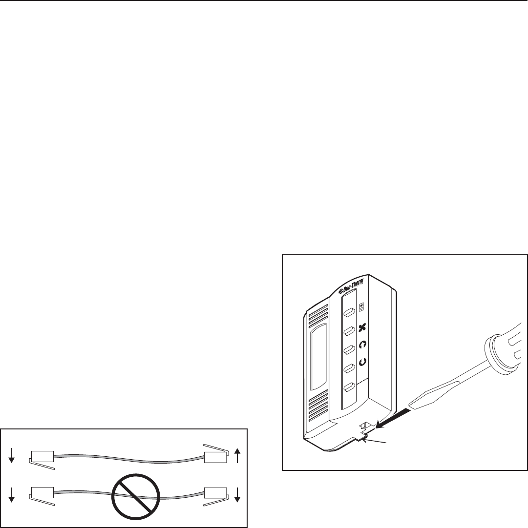
Note: RJ-11 connectors must be wired identically
on both ends. See FIG. 3.5.
4. Avoid locations close to doors that lead outside,
windows or adjoining outside walls;
5. Avoid locations close to supply registers and the
air from them;
6. Never locate CCC in a room that is warmer or
cooler than the rest of the coach - such as the
kitchen;
7. The major living area is normally a good location.
Note: If the system is to be used with a Remote
Temperature Sensor, the Comfort Control Center
may be mounted anywhere that is convenient in
the coach.
8. Try to avoid hard to reach or hard to see areas.
9. Refer to the instructions provided with the Remote
Temperature Sensor for details of installation.
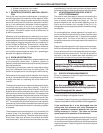
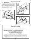
B. Comfort Control Center™ Installation
1. Carefully remove the base plate from the Com-
fort Control Center™. This may be accomplished
by inserting a small screwdriver under the tab on
the bottom edge of the front cover and gently pry-
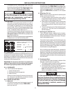
ing. See FIG. 3.6.
G. Plug the communications cable(s) into one of the
telephone jack(s) on the circuit board in the electri-
cal box. (It does not matter which one.)
3.4.3 COMFORT CONTROL CENTER MOUNTING
A. Location
The proper location of the Comfort Control Center
(CCC) is very important to ensure that it will provide a
comfortable RV temperature. Observe the following
general rules when selecting a location.
1. Locate the CCC about 54" above the floor;
2. Install CCC on a partition, not on an outside wall;
3. Direct heat from lamps, sun or other heat produc-
ing items will cause erratic operation and tem-
peratures;
FIG. 3.6
Insert Screwdriver
under Tab
Insert Screwdriver
under
Tab
M
O
D
E
MODE
FA
N
FAN
U
P
UP
D
O
W
N
DOWN
O
F
F
O
N
OFF
ON
Z
O
N
E
ZONE
TE
M
P
TEMP
2. Insert the control cable through the hole in the
base plate and mount the plate to the wall with
the two screws provided. Check the alignment to
ensure level installation.
3. Install the control cable RJ-11 connector into the
back of the Comfort Control Center™ and gen-
tly press onto the base plate.
4. If a Remote Temperature Sensor is to be used,
the connector end must be routed to the electri
cal control box and connected to the color match-
ing plug on the relay board.
5. If a furnace is to be controlled by the system, the
two furnace thermostat leads must be routed to
the electrical control of the air conditioner that will
control it. Make sure at least 15" of the furnace
thermostat wires extend into the electrical con-
trol box.
FIG. 3.5


